Continue to Site

Welcome to our site!

Electro Tech is an online community (with over 170,000 members) who enjoy talking about and building electronic circuits, projects and gadgets. To participate you need to register. Registration is free. Click here to register now.

  • Welcome to our site! Electro Tech is an online community (with over 170,000 members) who enjoy talking about and building electronic circuits, projects and gadgets. To participate you need to register. Registration is free. Click here to register now.

Adding sensitivity adjustment to an electret mic

Status
Not open for further replies.

Fenris

New Member
Hi all
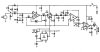
Just a quicky. On the picture attached I have added a variable resistor to
the mic input of the circuit(left). The supposed Idea is to be able to adjust the sensitivity of the electret mic. The main direction being to reduce the sensitivity. Is this a valid train of thought or the hopeless meanderings of
a hopeless novice?

regards

Fenris
 
You didn't attach a schematic.

The variable resistor needs to be an AC volume control without affecting the DC.
 
sorry about that heres the schematic.

regards

Fenris
 

Attachments

  • vader voice mod2.JPG
    vader voice mod2.JPG
    40.6 KB · Views: 1,221
The pot at the mic affects its DC voltge and current. Then I think the mic will be very distorted.
Use a coupling capacitor from the mic to the top of the volume control. Then another coupling cap from the slider of the volume control to the input of the opamp.

The lousy old LM358 is too noisy (hissss) for a mic preamp. Use an audio dual opamp like a TL072 instead. Maybe the lowpass filter removes some hiss.

The 555 and analog switch turn the mic on and off at a variable rate. Why?
 
That's a poor way of doing it.

Here's the right way of doing it.
 

Attachments

  • Corrected AMP.GIF
    Corrected AMP.GIF
    16.1 KB · Views: 1,063
Hi Hero,
The pot now steals some of the current that is supposed to power the electret mic. With DC in the pot then it makes noise when it is adjusted.
Add a coupling capacitor between the mic and the top of the pot.
 
Hi Hero,
The pot now steals some of the current that is supposed to power the electret mic.
Another option would be to use the pot for the 10k current limiting resistor or just use a 100k pot so the amount of current stolen is negligible.
 
Yes but it's always best to not have dc in the pot if you can afford the cap.

and ele. mics get noisy if the dc limiting resistor is too large.
10k is already as big as you want.

(the source is not specified but my tests years ago were for 9 vdc)
 
Last edited:
"unusable"? I don't understand.
Hero999's second option having the 10k and 100k pot in series (mic at junction, cap at wiper) is not so bad.
 
"unusable"? I don't understand.

It will make a loud crackling noise everytime you turn it, and as it's directly on the mike input it will be LOUD. NEVER feed DC through a volume pot.

Hero999's second option having the 10k and 100k pot in series (mic at junction, cap at wiper) is not so bad.

It's feeding DC directly through the pot, it's terrible - feed the top of the pot via a capacitor, or (even better) do the volume control later on, or in the feedback loop of the opamp.
 
Hi All

Thats quite a debate! Thanks for your input.


The 555 and analog switch turn the mic on and off at a variable rate. Why?

The circuit has already been heavily modified with a TDA2003 amplifier and sound to light unit attached, it's on here elsewhere from technical queries
I had as i got it sorted with the forums help. Basically the main circuit as seen
is a 'robot voice' changer. With the added amplifier and sound to light unit it is
now being used by around 30 people who have fitted it into their full size Dalek's. Google Dr Who if your not familiar with it. The LM358 due to it's 'rough' function actually 'enhances' the sound wanted a raspy, metallic type
voice on top of the 'chopping' effect but the TL IC you refer to is on my list of suitable replacement parts. The circuit works great for it's intended use but I was just wondering if it was possible to tweak the input of the mike
so that loud external noises (outside the prop itself) aren't picked up to easily
by the mic, also because of the close confines of the prop careful positioning and installation methods for the speakers have to be observed to avoid feedback without having to lower the output volume to the detriment of the 'performance'. A graphic equalizer inline would allow the frequency's that cause any feedback to be controlled but the whole point has been simplicity for the guys (& girls) who decide to build this design. It has been pointed out that a highly directional mic is preferable but if I can offer information of how to 'tweak' the design in the event of having an omni-directional or just plain too sensitive a mic it will be all to the good. I have a really good headset from a call center which I have modified with 2 Jack plugs to use with the design and I can stand 3 feet behind the speaker, which is on the kitchen counter, and have the volume at a very loud level without feedback unlike the
£9.99 headset I had first which could pickup a mouse fart at forty paces in the house over the road and have feedback with the volume appreciably lower than I can have it now. Any hoo I will try the coupling cap from mic to pot as well as the rejig just behind the pot. values for the additional cap would be?

regards

Fenris
 
You could add two back-to-back diodes in the negative feedback loop of the 1st opamp to clamp loud external noises and add a buzzy distortion to a loud voice.
 
Thats an idea I am aware of but I'm also trying to cater for the commonest
setup used by the gang which is PC type headsets. Thanks for the suggestion.

regards

Dave
 
Hi There

Would the feedback loop be where the 470K resistor is between pins 1 and 2?
Yes, connect two 1N4148 diodes back-to-back in parralel with the 470k resistor to clamp the output of this opamp to about 0.7V peak.
 
Hell Fire! I worked it out?!?!?! :D Thanks for the heads up I will experiment
with this idea. Thank you. So it would look like as in the picture attached?

regards

Fenris
 

Attachments

  • Corrected AMP.GIF
    Corrected AMP.GIF
    17.1 KB · Views: 393
Last edited:
No, maybe I should have said, "in parallel but with opposite polarities".
The diodes must be in parallel one with reversed polarity to the other. They are both in parallel with the 470k resistor.
 
Status
Not open for further replies.

Latest threads

Back
Top