Continue to Site

Welcome to our site!

Electro Tech is an online community (with over 170,000 members) who enjoy talking about and building electronic circuits, projects and gadgets. To participate you need to register. Registration is free. Click here to register now.

  • Welcome to our site! Electro Tech is an online community (with over 170,000 members) who enjoy talking about and building electronic circuits, projects and gadgets. To participate you need to register. Registration is free. Click here to register now.

ADC question.

Status
Not open for further replies.

alphadog

Banned
Hello guys.
i'm facing a wierd problem with ADC.
Its an ADC with the below characteristics:
capture-jpg.27222


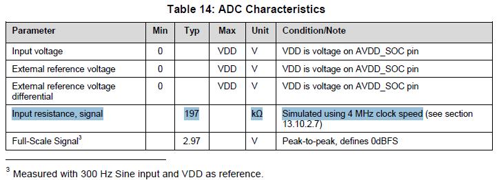
I tried circuits A and B as inputs for the ADC:
adc-jpg.27905


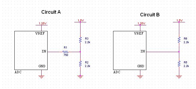
In circuit A, ADC showed 0.21V stable,
In circuit B, ADC showed 0.749V stable.

Does anyone know why in circuit A it showed such a low voltage?

Thank you.
 

Attachments

  • ADC.jpg
    ADC.jpg
    28.4 KB · Views: 259
Last edited:
Well, now that i measure the resistance of the 750 ohm resistor, the multimeter doesnt show resistance.
Could it be that the resistor increased its resistance, but still isnt being a cut-off so circuit B still managed to apply 0.75V on ADC?
 
The ADC characteristics are described in the table above.
Are there any other properties you need to know?
I'd like to hear :)
 
I dont have the part-number of the ADC, its samples I got here, and the supplier is available only Monday.
These were real measurements.

It would also help me to know what more information you need about ADC, i'm sure i can provide you with it, and i'll also learn for myself what should i look for.
 
If you don't have the parts then how are you measuring them? Where did you get the datasheet snippet? What's written on the part samples?
 
The voltage is dropping due to the 750 ohm resistor. The first R3 and R2 create a voltage divider that cuts the signal voltage in half since they are both the same value. That's what gives you the .749v on circuit B.

Now that voltage is applied across another resistor, 750 ohm, which will drop the voltage more, based on how much current the ADC is drawing. I'll let you figure out how much current the ADC is pulling by using Ohm's Law. :)

EDIT: Wow, that's a lot of current for an ADC. Now I think something is amiss...
 
Last edited:
The voltage is dropping due to the 750 ohm resistor. The first R3 and R2 create a voltage divider that cuts the signal voltage in half since they are both the same value. That's what gives you the .749v on circuit B.

Now that voltage is applied across another resistor, 750 ohm, which will drop the voltage more, based on how much current the ADC is drawing. I'll let you figure out how much current the ADC is pulling by using Ohm's Law. :)

EDIT: Wow, that's a lot of current for an ADC. Now I think something is amiss...
Since it worked with a 1.1kΩ source, I think the 750Ω resistor is mislabeled, being misread, or is just open. Alphadog alluded to some problem:
Well, now that i measure the resistance of the 750 ohm resistor, the multimeter doesnt show resistance.
but I didn't understand what he meant.
 
Since it worked with a 1.1kΩ source, I think the 750Ω resistor is mislabeled, being misread, or is just open. Alphadog alluded to some problem: but I didn't understand what he meant.

I meant that it semms like its resistance is too large for the multimeter to measure.
But, if R1 really got burned due to bad soldering, so how come Circuit B works?
 
I meant that it semms like its resistance is too large for the multimeter to measure.
But, if R1 really got burned due to bad soldering, so how come Circuit B works?
I don't see why the results of one test would affect the results of the other.
Why don't you repeat the test?
 
Status
Not open for further replies.

New Articles From Microcontroller Tips

Back
Top