Continue to Site

Welcome to our site!

Electro Tech is an online community (with over 170,000 members) who enjoy talking about and building electronic circuits, projects and gadgets. To participate you need to register. Registration is free. Click here to register now.

  • Welcome to our site! Electro Tech is an online community (with over 170,000 members) who enjoy talking about and building electronic circuits, projects and gadgets. To participate you need to register. Registration is free. Click here to register now.

ADC circuit problem.

Status
Not open for further replies.
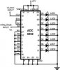
i have checked this circuit now by providing 500khz clock signal from 89c52 microcontroller and analog input in the form of voltage from a variable resistor connected to 5v dc and ground.... but .... the above circuit is not working :-( can any one please tell me the reason.
 

Attachments

  • adc0808.jpg
    adc0808.jpg
    11.8 KB · Views: 857
Last edited:
I think the ALE input is edge sensitive not level. If so then the A,B & C inputs may not be read.
 
You might check to see if your LEDs are in backwards.
and
The ADC0808 can not pull up hard. (500uA?) so the LEDs will not be bright. Check with a meter to see if some are at 0 volts and some are at 1.4 volts.
 
The LEDs in my circuit are connected in right direction. i checked the outputs of the ADC with a digital meter but the out puts are all 0v. means it is not generating the output.
can you please tell me what should be the maximum voltage at the analog input. and what should be the clock frequency provided to the ADC?
 
oh thank you MR ronsimpson ... you was right ,,, the problem was with ALE wich i pulld high according to the diagram. when i pull the wire out of positive rail/bus of bread board; the ALE got a High to Low transition and Lacthed the address and data abruptly transfered to the output pin and LEDs glow out :) thanks again.
 
I think the ALE needs a edge so you could connect it to EOC so it will get an edge every conversion.
 
Here is the text for that circuit.
Normally analogue-to-digital con-verter (ADC) needs interfacing through a microprocessor to convert analogue data into digital format. This requires hardware and necessary software, resulting in increased complexity and hence the total cost.
The circuit of A-to-D converter shown here is configured around ADC 0808, avoiding the use of a microprocessor. The ADC 0808 is an 8-bit A-to-D converter, having data lines D0-D7. It works on the principle of successive approximation. It has a total of eight analogue input channels, out of which any one can be selected using address lines A, B and C. Here, in this case, input channel IN0 is selected by grounding A, B and C address lines.
Usually the control signals EOC (end of conversion), SC (start conversion), ALE (address latch enable) and OE (output enable) are interfaced by means of a microprocessor. However, the circuit shown here is built to operate in its continuous mode without using any microprocessor. Therefore the input control signals ALE and OE, being active-high, are tied to Vcc (+5 volts). The input control signal SC, being active-low, initiates start of conversion at falling edge of the pulse, whereas the output signal EOC becomes high after completion of digitisation. This EOC output is coupled to SC input, where falling edge of EOC output acts as SC input to direct the ADC to start the conversion.
As the conversion starts, EOC signal goes high. At next clock pulse EOC output again goes low, and hence SC is enabled to start the next conversion. Thus, it provides continuous 8-bit digital output corresponding to instantaneous value of analogue input. The maximum level of analogue input voltage should be appropriately scaled down below positive reference (+5V) level.
The ADC 0808 IC requires clock signal of typically 550 kHz, which can be easily derived from an astable multivibrator constructed using 7404 inverter gates. In order to visualize the digital output, the row of eight LEDs (LED1 through LED8) have been used, where in each LED is connected to respective data lines D0 through D7. Since ADC works in the continuous mode, it displays digital output as soon as analogue input is applied. The decimal equivalent digital output value D for a given analogue input voltage Vin can be calculated from the relationship.

[N.B In this example i have tried to show only for IN0 channel, by selecting A, B, C you can also test the other Channels. ]
 
Status
Not open for further replies.

Latest threads

Back
Top