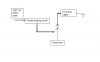
Hi guys, Im trying to do this project in which there is an AC sensor which will sense the high voltage Mains connection and then give a DC as output.
I know we can use the Relays to do this. but due to the power consumption of the relays, I thought there could be another way.
The circuit needs to be isolated from the mains (for safety reasons).
I even thought of useng a hall sensor to sense the AC and then use its output to conrtol other circuits.
any ideas?
Please let me know if im on the correct path.
Mat