Continue to Site

Welcome to our site!

Electro Tech is an online community (with over 170,000 members) who enjoy talking about and building electronic circuits, projects and gadgets. To participate you need to register. Registration is free. Click here to register now.

  • Welcome to our site! Electro Tech is an online community (with over 170,000 members) who enjoy talking about and building electronic circuits, projects and gadgets. To participate you need to register. Registration is free. Click here to register now.

AC to DC Converter required

Status
Not open for further replies.

babzog

New Member
Hey folks!

First post... please be gentle. I know very little about electronics theory or design and have a project to complete quickly and for which I'd be willing to pay.

First, the background. I'll try to be quick and summarize the current situation. If you're scratching your head.. it's probably because "I didn't know that at the time". LOL I've been catching up today!

I have a WaterFurnace, circa '91, that has a DC control board (I didn't know that at the time). The furnace wasn't working so I called my heating contractor. He told me the thermostat was done and I needed a new one. He had one in the truck (not the right one, but one that would do for the present) and wired it in. I got a quote for the right one, shopped around and picked up one locally. I wired it in last night and things start working.

Well, mostly. The instructions were unclear about a couple of things and I don't know why the call for service light comes on briefly when he unit switches off, so I call my contractor back for a looksee and verification. He says it's all wired correctly and confirms that it's supplying 24VAC to the terminals.

In the meantime, I called Waterfurnace to get some info and they tell me about the DC board in my old model and that I need a DC thermostat (of which, only one manufacturer still makes them and boy - are they pricey!) My contractor verified the DC board's presence and neither he nor the guys at Waterfurnace know why it's operating (but they both said that's the reason for the sporadic "call for service" indicators).

Anyway... all that backstory to come to this. I don't want to install an ugly DC stat with absolutely no features when I can use a nice modern one instead. Not unless I absolutely have to be dragged, kicking and screaming, into acceptance. I have plans for down the road, which include installing a Honeywell VisioPro IAQ to control the furnace, the VanEE and a humidifier down the road, all while eliminating wall clutter.

The specs for the original (dead) thermostat indicate:

Power Requirement: 18-30VAC, 10ma
Control Outputs: 15ma @ 22VDC max.

And the specs for the White Rodgers indicate an input of 24VAC from the transformer. I've been told that the thermostat steals power from the transformer hookup and converts it to DC for its own internal use. I've also been told that the thermostat relays are mechanical - switching whatever is put through them.

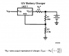
The first thought that comes to mind then, is converting the 24VAC from the transformer to 22VDC at 15ma (max).

the other thought that comes to mind, is to leave the 24VAC in place and convert the signals from the thermostat from 24VAC to 22VDC before connecting to the furnace.

Not sure what's easier, but it seems the latter approach - delivering what would be expected - would be the safer one. There would be up to 6 converters required, including the fault indicator.

What do you think?
 
You need to post the original schematic for the thermo and furnace.
It'd be good if you can get control board schematics also.
With all info, in principle, some sort of interface circuit could be designed.
 
Hi!

I can scan in and post the schematic for the furnace, which includes the control board. I have no schematics for the t-stat... just the specs for the original. I will do that shortly.

Cheers!

Here's the schamtics:

Page 1, incl control board

**broken link removed**

Page 2

**broken link removed**
 
Last edited:
Anyone have an idea of how I can step down 24VAC to 22VDC? I presume it's possible, I just have no idea how to figure it out. Is noone interested in making a few bucks for what should be a simple set of circuits? Donation to fav. charity? Postcard? Pizza?
 
Just kinda a shot in the dark, I don't have time to really study the schematics you posted, as I am on my way to work, but a bridge rectifiers will convert your 24v AC to DC, and a simple LM317 voltage regulator can be set to give you the 22V you need. You may also want to add a filter capacitor to the circuit to smooth out ripples.
 
You might try fixing the old 'stat. If it's totally dead it might be the power supply section. Post photos of the guts of it.

Ask the furnace manu. how much a new controller board costs.
Each time you mess with this thing there is some small chance that you will clobber the uP or some other costly component.
If the chance is 10% then you are gambling 1/10 the cost of the board, each time.

OK, so in the upper left corner of the upper schematic the AC goes into the T-stat on terminals R and C of P1, and the DC goes into and out of the uP on the other six P1 terminals.

If you want all the functions that the old dead T-stat allows you, you need to find a new T-stat that does the same functions. Then, conditioning the AC output of the new equivalent T-stat into usable DC should be easy.
Also, does the new T'stat inject AC into the furnace or just present contact closures to the furnace?

I'd help if you know the V in, and the current in, to the uP for a valid 1 or 0 state. See if you can get numbers off the uP case.

Also, which of these do you think you have?
**broken link removed**
It looks like you have cooling and 3 stage heating, 4 stage if you count the auxiliary electric heat.
I assume this is a heat pump system?

You might ask
HVAC-Talk: Heating, Air & Refrigeration Discussion - Powered by vBulletin
about the standard meanings for the letter designations (Y1, Y2, etc.) of the six terminals that go to the uP. The first post is at the bottom. Don't let on that this is a do-it-yourself project. Phrase your words carefully. Read some first posts first to get a feeling for what these guys tolerate. Read their forum disclaimer.
They might also find you a low cost equivalent T'stat for this furnace.
 
Last edited:
Look Babzok, here is the circuit you need


**broken link removed**

At the left, you can see the transformer, it says 28V but ignore that. Then, the diodes in diamond shape, that's called a bridge rectifier, it converts AC into DC. The LM317 its a voltage regulator, you should select the desired output voltage (22V) turning the pot shown in the circuit (4k7)

Anyway, I don't understand why do you need 22 VDC, didn't you said that the ugly unit used DC, and the cool one used AC?

edit: I remember the LM17 needs an input voltage >=3 volts superior to the output, so I'm afraid this thing may not work.

2nd IDEA:
Why you don't try to open the transformer? Inside the box you'll find the transformer, and a regulator circuit. We can modify that circuit to give the desired 22VDC
 
Last edited:
Swap the 240R for a 91R, the LM317 requires <120R to work properly, use 240R is for the more expensive LM117.

Swap the 4k7 pot for a 1k5 fixed resistor for 22V.

For only 15mA of output current the huge 2200µF capacitor can be reduced to just 33µF assuming the minimum transformer voltage is 24V.

EDIT:
Does it need to work down to 18VAC?

The minimum input voltage for this circuit to work properly is 18.5V with a 2200:mu:F filter capacitor - the dropout voltage of rhte LM317 is just 2V at such low currents. If 18V is required you could use Schottky bridge rectifier or a low drop-out regulator.
 
Last edited:
Swap the 240R for a 91R, the LM317 requires <120R to work properly, use 240R is for the more expensive LM117.

Where did you get this from?

All the datasheets I'm looking at (LM317L, LM317HV, LM117/317 from NSC) all give the same examples with 240R, and don't differentiate anywhere between the 117 and 317 for R1 that I can find. Many of their application examples use 240R for both the 117 and 317. In some of the examples they use 120R, but again, with either part. I've always used 240R and they've always worked flawlessly....

Care to shed any light on your information? :)
 
I got this from the datasheet.

The circuit on the datasheet is for the more expensive LM117 which is clearly labled on the schematic.

Refer to the minimum load in the electrical characteristics section of the datasheet, page 4 for the LM117 and page 5 for the LM317. The LM117 has a maximum minimum load current of 5mA and the LM317 has a maximum minimum load current of 10mA. If the load is under the maximum minimum load current then the regulator won't regulate properly under light loads and will probably output a higher voltage than it should.

R1 sets the minimum load current, the minimum referance voltage is 1.2V, therefore the minimum load current = 1.2/R1.

1.2/120 = 10mA
1.2/240 = 5mA

This means that for the LM317 R1 should be <120R and for the LM317 R1 should be <240R. I chose 91R for R1 in this instance for convenience's case as it means that for an output of 22V, R2 = 1k5 which is a standard E24 value.

I generally keep R1 above 91R in all of my LM317 designs because it keeps the quiescent current down.

In some instances I might choose a higher value than 120R for R1 (not too high though as Iadj starts to take effect) but that's because I know the circuit connected to it will always draw >10mA. For example if I have an LED connected to the output I might make R1 9k1 and R2 15k which is acceptable as the LED would be drawing 10mA.

https://www.electro-tech-online.com/custompdfs/2008/11/LM117.pdf
See page 6 of the datasheet.

EDIT:
edit: I remember the LM17 needs an input voltage >=3 volts superior to the output, so I'm afraid this thing may not work.
It isn't that simple, the dropout voltage depends on the current being drawn and the temperature. It's just that many of the parameters on the datasheet e.g regulation, ripple etc. are specified when the input is 3V>Vout so it's a good idea to use it as a rule of thumb.

For example if the die temperature is between 25°C and 100°C, the dropout voltage is just 2.25V.

In this case the current is under 20mA so the dropout voltage will be better than 1.75V but aiming for 2V is a pretty safe bet.

lm217-dropout-gif.11469
 
Last edited:
1.2/120 = 10mA
1.2/240 = 5mA

Cool, I get that. Thanks for the info.

(The fact that they use 240R for some of their LM317 examples, however, is either a mistake, or perhaps they're not too concerned about it :confused: )
 

Attachments

  • 317.PNG
    317.PNG
    8.5 KB · Views: 123
Hey folks,

Sorry for not responding... have been away and dealing with disreputable building contractors this week. Very stressful.

Okay, so I took some shots of the old (dead) t-stat. Doesn't really show much (to me). Pics below (sorry they're not very good - photography is not my forté).

I understand what the terminals are for (other than L - the one used for signalling faults - not sure which way the power flows on that one).

L - Fault signalling
Y1 - Stage 1 heat (in my case, compressor)
Y2 - Stage 2 heat (in my case, shuts off water heater to divert all heat to the house)
W - Aux heat (also for Stage 3 [stages 1+ 2 + Aux = Stage 3] and emerg heat)
G - fan control
O/B - reversal valve (reverses the water flow for cooling mode)
R - 24AC from transformer
C - Common (to common side of transformer)

I also don't know specifically if the t-stat provides contact closures or power to the furnace. The specs for the furnace seem to indicate that the uP has DC lines to the t-stat terminals and the manuf confirmed that's it's a DC board and thus requires a Robert Shaw 300-202 t-stat (which is way more expensive than the most advanced Honeywell t-stat out there, ugly as sin and provides no features whatsoever other than maintaining a temp).

In the meanwhile, my HVAC guy had temporarily installed a new Honeywell t-stat (which I replaced with a White-Rodgers t-stat that has the correct 3heat/2cool capability, and which I'm replacing again next week with a Honeywell VisionPro IAQ) and it was working... so I don't know what's going on. Why would the manuf tell me one thing while the opposite appears to be true? The manuf also said that a new t-stat is cheaper than retrofitting the furnace, so again, they're either out to lunch or telling me good things. I just don't know at this point; I don't have a good HVAC contractor who knows this unit, I don't have faith in the manufacturer's tech assistance and the guys over at hvac-talk simply aren't interested in helping folks like me (they just want to protect their industry in the manner of the stonemasons of yesteryear... my thread on this topic was locked down for talking about it). So, I feel like I'm caught between the proverbial rock and hard place.

Anyway, that's my gripe... not bitter, just puzzled by the matter at hand.

I can get a shot of the uP but aside from that, I have no idea what the specs are for the input/output voltages. If you can suggest some sources or questions to ask of the manuf, I will do so and post back my findings. What I know at this point, is what is printed in the original t-stat manual:

Power Requirement: 18-30VAC, 10ma
Control Outputs: 15ma @ 22VDC max.

Thanks again for looking into this with me!

Overall view of the old t-stat (board is normally a "sandwich" with the LCD facing out and the other board in behind):
**broken link removed**
The remaining pics are upside down (light fell better on the components, plus it makes reading the chips easier). References at to the above overall pic.

Top of "behind" board:
**broken link removed**
Bottom of "behind" board:
**broken link removed**
Bottom of "front" board:
**broken link removed**
Top of "front" board:
**broken link removed**
 
Status
Not open for further replies.

Latest threads

New Articles From Microcontroller Tips

Back
Top