Continue to Site

Welcome to our site!

Electro Tech is an online community (with over 170,000 members) who enjoy talking about and building electronic circuits, projects and gadgets. To participate you need to register. Registration is free. Click here to register now.

  • Welcome to our site! Electro Tech is an online community (with over 170,000 members) who enjoy talking about and building electronic circuits, projects and gadgets. To participate you need to register. Registration is free. Click here to register now.

AC to DC conversion to drive dc motor.

Status
Not open for further replies.

encorepistol

New Member
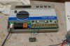
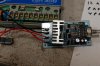
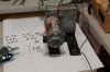
First off lets just say I'm what you may call electronically challenged. OK I'm working on a project for an incubator that uses a simple water sprinkler timer that outputs 28 volts ac. This timer is used to trigger the times that the motor is to turn on. Well to get the timer to convert to dc volts I used a bridge rectifier. The problem lies within a couple other parts involved I think. First off the motor needs to turn both cw and ccw, also the motor turns too fast so I picked up 2 pwm controllers to adjust the speed independently or so I thought. So I have station 1 terminal and ground of the timer hooked up through one bridge rectifier then to the control board and onto the motor, then I have station 2 terminal and ground of the timer hooked up the same way but the wires to the motor are reversed. The problem I have is when the timer powers up the fuse blows right away. If I undo one the wires to the station that isnt energized everything works but as soon as you wire everything together she goes pop. Will this setup even work? Was thinking maybe a diode or more somewhere but like I said at first im pretty much clueless.
 
The bridge rectifier to change from AC to DC to run the motor is fine.

As you have a PWM controller, it would be a good idea to add a smoothing capacitor to the input of the PWM controller. The capacitor needs to be rated at 50 V or so, and should be about 5000 µF for each amp that the motor draws.

You cannot connect the outputs of two PWM controllers together, and certainly not in different directions.

I suggest that you find some 24 V relays. They need to be two pole relays, so that they have two contacts that switch at the same time. Wire the coils of the relays to the output of the bridge rectifiers. Then connect the motors to the controllers though the contacts of the relays.

That way, only the active controller is connected to the motor.

28 V rectified is probably nearly 40 V, so if these run for more than a minute or so your relays may get a bit warm. You can add a resistor in series to reduce the voltage but the value depends on which resistor you use.
 
If you search here (ETO) you will find more practical Incubators concepts, but if want to go with your design, you may use a Limit Switch in both stations and do not forget to use a diode for freewheeling when motor stops to protect the contacts of your switching device.
 
You couldnt point me to the parts you would use could you? Im already into this too deep to switch to a different idea now really. I never checked the voltage out of the rectifier so Im not sure of the voltage there. I do have to add a couple limit switches to stop the turning racks at their farthest points of movement but why would I need a diode if Im breaking the flow of current to the motor?
 
well I thought I had it figured out but after reading again I think I overlooked the relay style. The relay needs to be a spdt correct? Now I am completely stumped as to how everything would wire together also. I'll try to get a pic of what I have so you can see what I'm working with.
 
Here are pics of the sprinkler timer , one motor controller ,and the motor itself.
 

Attachments

  • DSC_0001 (Small).JPG
    DSC_0001 (Small).JPG
    55.3 KB · Views: 269
  • DSC_0002 (Small).JPG
    DSC_0002 (Small).JPG
    55.9 KB · Views: 212
  • DSC_0003 (Small).JPG
    DSC_0003 (Small).JPG
    41 KB · Views: 218
Alternate method

There are a couple of problems with what I see you have done so far. Mainly caused because the timer is not designed for this.

If you would like a simpler way of doing it, I have attached a PDF. I can't tell you the value of the resistor because I don't know the spec's of your motor. Because the half wave rectification will reduce the average voltage to the motor, you may not need it. Take a photo of the label on the motor and I can probably give you a better idea.

The limit switches are normally closed momentary contact type.

When output 2 is active the motor travels in one direction until the limit switch opens. Then when output 3 activates the motor travels in the opposite direction.

There may be problems if you try to activate 2 and 3 together so make sure you never do that.
 

Attachments

  • Motor timer.pdf
    8.1 KB · Views: 302
Here is a pic of the motor label. I'm lost on the schematic kinda still. would I not use the rectifiers with this or the pwm controllers? Would #1 be common? I also have some 1N5402s would these work?
 

Attachments

  • a.JPG
    a.JPG
    34.5 KB · Views: 213
Also If I just drop the voltage wouldn't it reduce the torque of the motor? The motor runs at 40 rpm at 24 volts but am trying to get it down to 1 or less.
 
Torque

I hadn't realized that you were trying to decrease the speed that much. If you require torque, the only way to do that is with a gearbox. Even your pwm controller reduces the average voltage to the motor which will decrease the power going to the motor which is proportianal to the torque.
 
Dont know what I.was thinking but I knew I was going to have to use the limit switches anyway but when I was checking everything I just hooked all the wires together,duh!!! The way I had it shoild work without the relays when I put the wiring through the limit switches after the pwm controllers correct? I think I answered my question already because it worked when I hooked it up one at a time.
 
It wont require a terrible amount of torque since the racks are balanced and as long as I keep the weight even on both sides or close to it It should be ok.
 
Well I went ahead and ordered a different motor that I found that runs at only 1.4 rpm at 24v. the motor is a Molon CHM-2401-1-1M. Hopefully this way I can do away with the pwm controllers and re-sell them. Do you have any idea on the resistor size I should use with this motor in your schematic.
 
Got it working last night! Id left it for a little to make a couple different parts but its working like a charm. Thanks for all the help!!!
 
Status
Not open for further replies.

Latest threads

New Articles From Microcontroller Tips

Back
Top