Continue to Site

Welcome to our site!

Electro Tech is an online community (with over 170,000 members) who enjoy talking about and building electronic circuits, projects and gadgets. To participate you need to register. Registration is free. Click here to register now.

  • Welcome to our site! Electro Tech is an online community (with over 170,000 members) who enjoy talking about and building electronic circuits, projects and gadgets. To participate you need to register. Registration is free. Click here to register now.

AC motor reversing circuit

Status
Not open for further replies.

leonel

New Member
Hi...
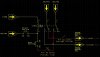
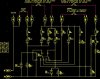
Can anybody tell me if the attatched circuit works as an AC motor reversing circuit?? I have problems using this circuit?
I have two contacts. "Fim de curso posição inicial" is in the beginning and is a NO contact. "Fim de curso posição final" is at the end and is a NC contact.
I have one start switch (close my circuit) that makes my motor run in one direction -->
One stop switch (opens my circuit) that makes my motor stops and run in opposite direction <--. If my motor goes to the end without anybody close stop switch, my contact "Fim de curso posição final" opens and my motor goes in <-- direction.
And another cycle begins when my start switch is pushed again!!!
 

Attachments

  • inversao_de_rota__o.jpg
    inversao_de_rota__o.jpg
    50.2 KB · Views: 2,903
AC motors are generally difficult to reverse, you can't just swap the leads round, like most DC motors - and it varies completely with different motor types.
 
If you know some circuit or some site that can help me it was good...
I want to build a simple (cheap) AC reversing circuit!
 
Nigel Goodwin said:
AC motors are generally difficult to reverse, you can't just swap the leads round, like most DC motors - and it varies completely with different motor types.

Unless it is 3ph when swapping 2phase will change its direction
 
Many of the single phase, general purpose, fractional HP motors here in the US have a junction box within the motor - and within this box the leads can be changed to reverse direction. Diagrams indicating which leads to change are provided with the motor. Sometimes the leads are brought out to a reversing switch. As Nigel recommends, you need to know exactly what kind of motor you have before you can go much further. There is no "one size fits all" answer to this question.
 
I don't know what you need to know exactly about my motor! It's a 1/3 HP one phase motor. Attatched is a typical representation schematic for a split-phase motor.
 

Attachments

  • motor_332.jpg
    motor_332.jpg
    33.3 KB · Views: 8,076
Try swapping the S1 and S2 connections.
My best guess is that the motor will then run in the opposite rotation.

JimB
 
JimB said:
Try swapping the S1 and S2 connections.
My best guess is that the motor will then run in the opposite rotation.

Yes, I would assume so as well, the start winding is probably to make sure it starts in the correct direction.

If you ever look at the turntable in your microwave oven, those don't have start windings, so can rotate either way at random.
 
I kown that as result of the connection illustrated in figure between both windings (M2-S1 and M1-S2), the motor will start with a certain rotational direction. If reverse direction is desired, the connection between both windings must be changed as follows: M2-S2 and M1-S1.
My problem is doing that without triacs and PIC! I know how to do with those components, but only with switches, resistors and capacitors for me it's much more complicated :?
Anybody can help me???
 
leonel said:
I kown that as result of the connection illustrated in figure between both windings (M2-S1 and M1-S2), the motor will start with a certain rotational direction. If reverse direction is desired, the connection between both windings must be changed as follows: M2-S2 and M1-S1.
My problem is doing that without triacs and PIC! I know how to do with those components, but only with switches, resistors and capacitors for me it's much more complicated :?
Anybody can help me???

Just use a relay!, a DPDT one will do the job, as would a double pole changeover switch (same thing really).
 
That's why my first picture, but you said (and i agree with you) "AC motors are generally difficult to reverse, you can't just swap the leads round, like most DC motors - and it varies completely with different motor types."
Anf if for example my motor stays "stuck", i want that changes direction (to not overheat)
 
leonel said:
That's why my first picture, but you said (and i agree with you) "AC motors are generally difficult to reverse, you can't just swap the leads round, like most DC motors - and it varies completely with different motor types."

Yes, you can't just switch the supply to the entire motor, just reverse it to the start winding and see what happens.

Anf if for example my motor stays "stuck", i want that changes direction (to not overheat)

That's a completely different story, and is likely to be far more difficult to achieve!. Assuming it's moving something from one position to another?, you can use limit switches at the end - but this would only provide protection at the end of travel.
 
There's any way that for example i turn on one 24V relay and if my motor "stuck" this voltage reduces and turn off my relay?
 
It sounds like you want to operate the motor in a fixed direction until it reaches the end of travel or it becomes stuck, then you want to reverse direction - and I'll assume you want the same behavior.

You'll need something to indicate end of position - this can be a microswitch, magnetic reed switch, photocell or some other means of positively indicating position. You could just decide to ignore the end and let it become "stuck" but good practice is usually to indicate this differently and separately.

You'll need to define "stuck" so that you can figure out how to determine that. You could use a tachometer or some other indication of motor rotation so that you can decide it's stuck before it actually comes to a complete stop. That might be a nice feature. You might also look at motor current and time. High current for a long time implies "stuck" and your control system would react to that. You'd have to define what the current levels are - probably some experimenting is in order.

Once you know how to indicate "end" and "stuck" you can then move on. If the plan is to reverse the motor when it reaches the end or gets stuck you might also want to add a feature that prevents it from toggling back and forth should it really become stuck.

While I have yet to complete a PIC project I would have to say that some form of microprocessor control is a good solution here. This control might control a reversing relay or some solid state means of reversing your motor -if it can be reversed.

I hope this helps a little.
 
To be honest it helps me to calm down... Because i'm becoming a little confused because i know how to do with a microprocessor (PIC) but it's a little expensive solution to my project!
See this solution (i'm turning arond with this solution) to see what i can do!
Please try to help me to understand better this circuit or what it does (i think that's a possible solution, or something like that)
Thank's
 

Attachments

  • placa_ibico.jpg
    placa_ibico.jpg
    41 KB · Views: 580
Status
Not open for further replies.

Latest threads

New Articles From Microcontroller Tips

Back
Top