Continue to Site

Welcome to our site!

Electro Tech is an online community (with over 170,000 members) who enjoy talking about and building electronic circuits, projects and gadgets. To participate you need to register. Registration is free. Click here to register now.

  • Welcome to our site! Electro Tech is an online community (with over 170,000 members) who enjoy talking about and building electronic circuits, projects and gadgets. To participate you need to register. Registration is free. Click here to register now.

AC Coupling Audio Buffer

Status
Not open for further replies.

Nescafe

New Member
Hi All,

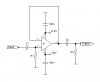
I have some questions regarding op amp audio buffer from the given schematic:

1. If the C1 around 220-1000uF & R1 100K, which is the better op amp for U1, BJT or FET input? With the Z behaviour of cap along with the frequency change, would You like to inform me what is the ideal one BJT input (low noise voltage) or FET input (low noise current)?

2. For C1 and C2, with value around 220uF-1000uF what is the right/correct electrolytic capacitor rated voltage needed (I have try with 6.3V, 16V & 35V and all are seems work?)? I'm aiming the phase shift at 10Hz as low as possible that's why I use large value cap but I'm not sure what voltage is the correct one, any direction how to calculate it?

Any reply, help, and explanation are really appreciated.

Thank You.
 

Attachments

  • AC Coupling.jpg
    AC Coupling.jpg
    23.8 KB · Views: 198
Input cap C1:

79.gif


So it depends on what is the lowest frequency you want your amp to pass. If you want to compute it, follow this link. 220uF or higher is overkill by several orders of magnitude.

To know what to use for C2, you have to tell us the value of R2.

The voltage rating of C1 depends on the DC voltage present at INPUT (if any)?
The voltage rating of C2 can be low because it has zero DC volts across it during operation .
 
Last edited:
Your capacitors are FAR too large in value, I suggest you try working out their reactance at the lowest frequency you wish to pass.

What EXACTLY are you trying to achieve?

Voltages just need to be higher than the highest voltage the capacitor will have across it during use - more than half the supply should be fine for coupling capacitors.
 
Input cap C1:

View attachment 89039

So it depends on what is the lowest frequency you want your amp to pass. If you want to compute it, follow this link. 220uF or higher is overkill by several orders of magnitude.

To know what to use for C2, you have to tell us the value of R2.

The voltage rating of C1 depends on the DC voltage present at INPUT (if any)?
The voltage rating of C2 can be low because it has zero DC volts across it during operation .

MikeMI,

Thank You, the DC in the input is unkonwn, depend on the DC offset of other equipment, can be anything but maybe the max is a few mV, so 6.3V cap is OK?

Nigel Goodwin,

Thank You, the goal is to achieve as small as possible phase shift in the 10Hz, and the bipolar I have in hand max 1000uF, seems good enough, just not sure the cap voltage needed, from MikeM answer above, the voltage rating needed should be higher than DC in the signal, I think most of the audio device should not have more than few mV DC so 6.3V is OK, am I right?

Thank You.
 
Last edited:
...the goal is to achieve as small as possible phase shift in the 10Hz, ...
For C1, a 10 uF capacitor would do that. You never said what R2 is?
 
After you turn on the power, how long are you willing to wait for it to begin passing normal audio? With 1000uF and 100K, you might have to wait for over 1 minute...

Bigger is not necessary better...
 
MikeMI,

Thank You, the DC in the input is unkonwn, depend on the DC offset of other equipment, can be anything but maybe the max is a few mV, so 6.3V cap is OK?

Nigel Goodwin,

Thank You, the goal is to achieve as small as possible phase shift in the 10Hz, and the bipolar I have in hand max 1000uF, seems good enough, just not sure the cap voltage needed, from MikeM answer above, the voltage rating needed should be higher than DC in the signal, I think most of the audio device should not have more than few mV DC so 6.3V is OK, am I right?

But why this obsession with trying to achieve low phase shift?, you may perhaps have noticed that no one uses crazily huge values for coupling capacitors - this is for very good and obvious reasons. As I said before, work out the reactance of the capacitors, and the reactance value they need to be.

There 'should' be no DC voltage on either the input or the output, as capacitors in the other equipment block any of that.
 
Hi Maxwell House Coffee,
You mentioned audio. Then the lowest frequency is 20Hz and an RC with -3dB at 10Hz (0.16uF into 100k ohms) will cause no obvious loss of 20Hz.
We cannot hear phase shifts.

There are very low noise Bjt opamps and there are very low noise Fet opamps. 100k is not high and it is not low so the type of opamp does not matter.
 
After you turn on the power, how long are you willing to wait for it to begin passing normal audio? With 1000uF and 100K, you might have to wait for over 1 minute...

Bigger is not necessary better...
Last night I try in breadboard again and yes the time delay is long enough, I switch to 100u and that's a lot of better :D

As I said before, work out the reactance of the capacitors, and the reactance value they need to be.
Yes I have try to calculate the reactance that's why I'm confuse with op amp choice, when in the low freq the ideal one is FET but in the higher freq the ideal one is BJT (noise)


Now I'm thinking of using AC coupling in the input only, lower the C1 cap to 100u or 47u and use larger R1 with value 1M or 2M, is there any downside audio wise (noise or THD) with larger value R1?

What I try to build are 7 cascade switchable circuits in series, I have try to spice and the output of last circuit is have larger phase shift, so I think the lower the better?

Hi Maxwell House Coffee,
You mentioned audio. Then the lowest frequency is 20Hz and an RC with -3dB at 10Hz (0.16uF into 100k ohms) will cause no obvious loss of 20Hz.
We cannot hear phase shifts.

There are very low noise Bjt opamps and there are very low noise Fet opamps. 100k is not high and it is not low so the type of opamp does not matter.
Hi audioguru, Thank You for the tips, and when use 1M or 2M for R1, is the op amp type still doesn't matter?

Once again Thank You, all the reply here is help me a lot.
 
I'm confuse with op amp choice, when in the low freq the ideal one is FET but in the higher freq the ideal one is BJT (noise)
There are very low noise BJT and FET input opamps. Pick one.

Now I'm thinking of using AC coupling in the input only, lower the C1 cap to 100u or 47u and use larger R1 with value 1M or 2M, is there any downside audio wise (noise or THD) with larger value R1?
47uF feeding 1M has a cutoff frequency for earthquake vibrations of 0.0034Hz and takes longer than 47 seconds to charge. We cannot hear frequencies below 20Hz but some speakers cause us to feel vibrations as low as 10Hz.
Coupling capacitors should be film type that do not cause the distortion and electrolytic absorption of electrolytic capacitors. But a film capacitor with a value as high as 47uF might not be available because it would be HUGE and very expensive. I use 0.33uF (330nF) film capacitors to couple audio in most of my circuits.
Resistors produce thermal noise. Higher value resistors produce more noise.

What I try to build are 7 cascade switchable circuits in series, I have try to spice and the output of last circuit is have larger phase shift, so I think the lower the better?
Repeat: We cannot hear phase shifts.
With 7 circuits in series then all the RC inputs and RC outputs reduce the low frequencies so you must calculate their values to be 7 times or 14 times the value of a single capacitor.

Hi audioguru, Thank You for the tips, and when use 1M or 2M for R1, is the op amp type still doesn't matter?
Some BJT input opamps cannot use high value input resistors because their bias current is too high. Please read the datasheet.
 
There are very low noise BJT and FET input opamps. Pick one.

Resistors produce thermal noise. Higher value resistors produce more noise.


Repeat: We cannot hear phase shifts.
With 7 circuits in series then all the RC inputs and RC outputs reduce the low frequencies so you must calculate their values to be 7 times or 14 times the value of a single capacitor.

Some BJT input opamps cannot use high value input resistors because their bias current is too high. Please read the datasheet.

Thank You audioguru, solved.
 
Status
Not open for further replies.

Latest threads

New Articles From Microcontroller Tips

Back
Top