MrDEB
Well-Known Member
Trying to learn something about transistor switches etc. SEE RANDOM CABINET LIGHTS post
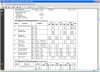
I attached a data sheet for a cd4029 counter. want to drive a transistor into saturation for best results but without frying the 4029 outputs.
looking at the output current am I to assume that the 4029 will source 1.6ma at 10v supply?
at 15v the 4029 will source 4.2ma??
I looked over my schematic and assume that I need to have the load connected to the emitter on a 2n2222. I have it connected to the collector.