Hi, all: I'm back after a long hiatus. Good to see the place is still around.
Current project (at least in the pencil-and-paper stage): building a working triangle-wave generator using only "discretes" (i.e., no ICs).
Disclaimer: this project is strictly for my own amusement, not for commercial or other "serious" use, so accuracy, etc., is not an issue at this point.
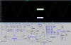
So here's what I've got so far: I'm using a multivibrator (my favorite simple oscillator) to drive two things, a gated current source and a gated current sink. The current source's load is a capacitor, used as an integrator to create a (hopefully) linear positive-going ramp. The sink is used to discharge the cap. Here's the circuit:
.gif")
and here's the LTspice plot from running the simulation:

So, not too bad for the 2nd pass, but there are problems:
Clearly I'm missing something here in my understanding of how all this stuff works, and would appreciate guidance here.
I like the multivibrator: a nice simple, fairly reliable source of square waves (conveniently of both polarities); the duty cycle appears to be 50%. The current source seems fairly elegant and seems to work well. But that discharge circuit: ugh.
Is there a simpler/more elegant way to do this? I'm open to suggestions.
BTW, my further motives for this circuit are to use it in such applications as fading LEDs, PWM control, maybe even a "poor man's" class D amplifier. (Yes, I know that wave would have to be pretty damn linear to reduce distortion!)
So I look forward to your ideas. The main thing here is to increase my understanding of electronics.
Current project (at least in the pencil-and-paper stage): building a working triangle-wave generator using only "discretes" (i.e., no ICs).
Disclaimer: this project is strictly for my own amusement, not for commercial or other "serious" use, so accuracy, etc., is not an issue at this point.
So here's what I've got so far: I'm using a multivibrator (my favorite simple oscillator) to drive two things, a gated current source and a gated current sink. The current source's load is a capacitor, used as an integrator to create a (hopefully) linear positive-going ramp. The sink is used to discharge the cap. Here's the circuit:
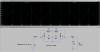
and here's the LTspice plot from running the simulation:
So, not too bad for the 2nd pass, but there are problems:
- The upward slope of the wave is pretty damn good, better than I expected from such a simple implementation. You can see the current waveform (purple trace) slopes down a little bit, but not too shabby, which leads me to believe that the up-slope of the triangle wave is fairly linear. The down-slope, however ... pretty much sucks. Has the typical exponential shape of a discharging cap, not a nice straight line.
- Much smaller problem, but the triangle wave never goes below about 3.5V. It would be nice to have it reference 0V, so probly needs to be level-shifted.
Clearly I'm missing something here in my understanding of how all this stuff works, and would appreciate guidance here.
I like the multivibrator: a nice simple, fairly reliable source of square waves (conveniently of both polarities); the duty cycle appears to be 50%. The current source seems fairly elegant and seems to work well. But that discharge circuit: ugh.
Is there a simpler/more elegant way to do this? I'm open to suggestions.
BTW, my further motives for this circuit are to use it in such applications as fading LEDs, PWM control, maybe even a "poor man's" class D amplifier. (Yes, I know that wave would have to be pretty damn linear to reduce distortion!)
So I look forward to your ideas. The main thing here is to increase my understanding of electronics.
")