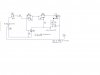
Hello all,the circuit presented is from a working(very well I might add) 200 Amp Power supply enclosed in a aluminium case.The front has a Volt Meter,power switch and the Pot in the circuit for volt adjust.The voltage source is from a bunch of 50Amp bridge rectifiers in parallel.This circuit has overload protection,whereas if the voltage goes below a certain point due to a BIG load it cuts the regulator out,this part I believe is the PNP.I can't for the life of me figure out how the rest of the circuit works.The TO-3's collectors go to case.When you put the positive lead on the base of a TO-3,and neg lead to case ground you will see an adjustable negative voltage.Now what perplexes me is the "In" of the 337 goes to the TO-3 base?? Also,the TO-3 in of unknown type.All I see is the motorola symbol,and "K70",no other markings but tests like an NPN,so its an assumption.I would like to replicate this circuit for a bechtop power supply,please someone shed some light as to how this circuit works..Thanks....")
P.S-The zener is of unknown value..
P.S-The zener is of unknown value..