Continue to Site

Welcome to our site!

Electro Tech is an online community (with over 170,000 members) who enjoy talking about and building electronic circuits, projects and gadgets. To participate you need to register. Registration is free. Click here to register now.

  • Welcome to our site! Electro Tech is an online community (with over 170,000 members) who enjoy talking about and building electronic circuits, projects and gadgets. To participate you need to register. Registration is free. Click here to register now.

A question about this circuit design

Status
Not open for further replies.

fzn10

New Member
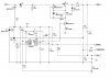
hey guys just wondering what the advanatages of using the three transistors in the circuit attached. This is a battery charging circuit, the MOD pin gives a square wave that is 5v(p-p). just wondering why not just use a mosfet. why not do this circuit with one snubber circuit and one transistor rather than a snubber and two transistors.

Thanks
 

Attachments

  • threetrans.JPG
    threetrans.JPG
    42.4 KB · Views: 172
The manufacturer of the power transistor (zetex) has been advocating the use of BJT's in switching circuits for a while - I'd link to their app note, but it's hidden behind a pile of javascript - look for AN22 over at www.zetex.com. It actually mentions the company who made the bq series chips (benchmarq, now part of TI).

I'm pretty sure Q2 and is there to speed up the turnoff of the power transistor. That aside, the voltage would still need to be translated in order to operate the mosfet, so Q3 would still want to be there, and you'd need something to turn the mosfet off properly since a simple resistor would probably be too slow for a switching regulator.

In short, you could replace Q1 with a mosfet and a little bit of rewiring if you wanted to, but you'll still need another two transistors to "prep" the 0-5V logic signal.

Lots of ways to skin the cat...

James
 
Status
Not open for further replies.

Latest threads

Back
Top