Electro Tech is an online community (with over 170,000 members) who enjoy talking about and building electronic circuits, projects and gadgets. To participate you need to register. Registration is free. Click here to register now.
Welcome to our site! Electro Tech is an online community (with over 170,000 members) who enjoy talking about and building electronic circuits, projects and gadgets. To participate you need to register. Registration is free. Click here to register now.
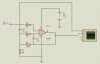
It is a useless circuit. As drawn, the output will sit saturated at ground because the inputs are both biased to ground because the Vss pin is also grounded.
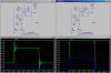
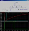
The circuit also functions as a strange bandstop filter, where frequencies under around 105Hz get amplified, and frequencies above 1kHz get passed without too much attenuation, but frequencies within a certain bandwidth centered around 142Hz get cut quite a bit. So it's like a low pass filter and a bandstop filter. It may also be that it was made to work as a low pass filter with a very sharp cutoff.
That is of course assuming that the input signal has at least some dc bias voltage as well as the ac signal.
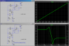
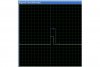
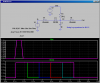
Ok, I see what is going on. You are overdriving the opamp by input-ing a pulse that has no bias component (so the opamp rails to ground), and the pulse is so big that it rails on the top-end, too. In the sims, I show the difference between constraining the pulse so that it does not over-drive the opamp vs what you are doing to it. Note the ringing in the former which is suppressed by letting the opamp slam into its internal limits. The delay comes principally from the opamp recovering from being so badly overdriven.
If you goal is to build a pulse stretcher, there are much better ways of doing it.
Note that in my sim I'm using a better opamp than you (mine is true rail-to-rail IN and OUT), and it has a higher GBW.
This site uses cookies to help personalise content, tailor your experience and to keep you logged in if you register.
By continuing to use this site, you are consenting to our use of cookies.

![ourdev_580283DXGK7N[1].jpg](/data/attachments/39/39213-6cca0e62f21591469daa869505c44ad5.jpg)