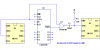
1.)When my counter IC (4029)counts from zero to one pin 7 Goes high (7.5v)
I want to use that rising edge to pulse a second circuit. Any faster way to get a pulse other than using the 555, if not is it okay to invert that pin 7 output and go straight to pin 2 Of the 555.
2.) Also another little problem, A backward count from zero to nine also makes pin 7 go high. I understand y it happens based on the counters 4 outputs but is there any way around it, that is: “zero to one: yes” “zero to nine: no”.
Thanks,
Haxxx.