Electro Tech is an online community (with over 170,000 members) who enjoy talking about and building electronic circuits, projects and gadgets. To participate you need to register. Registration is free. Click here to register now.
Welcome to our site! Electro Tech is an online community (with over 170,000 members) who enjoy talking about and building electronic circuits, projects and gadgets. To participate you need to register. Registration is free. Click here to register now.
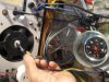
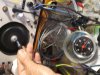
The VDO tacho on Ebay is very simmilar to the one I used & it came of a large diesel generator. The engine orig had a small ac generator run of the camshaft to drive the tacho. I removed the internal circuitry of the tacho & just used it as a meter driven by the freq to voltage converter. This worked very well on my diesel boat motor.
To drive the hall i used a small magnet out of a scraped signal level meter, If its glued to the engine shaft as in picture it will give a Nth then a Sth pole presented to the hall switch. The hall requires this to turn it on then off. Using one magnet it is easy to calibrate as in my early pictures using a small solenoid to drive the hall. Here the mains is 50Hz & gives a reading of 3000Rpm
This is the data sheet for your series of sensors. Something to note here is where the data sheet shows "South Pole-sensitive Switch or Bipolar Latch Available ". The sensor bebe used was a bi polar latch and thus he uses both poles. The N pole latches and the S pole unlatches to create his pulse. This would be the same as the MP101303 in the data sheet. If you use the MP101301 or MP101302 you only need the sensor to see the S pole and each time the S pole passes a pulse is generated.
Hi Ron, Thanks for the extra input on the diferent types of Hall devices. Daryl. All my Hall devices were salvaged from scraped VCRs for free, they were used as reel sensors.
This site uses cookies to help personalise content, tailor your experience and to keep you logged in if you register.
By continuing to use this site, you are consenting to our use of cookies.