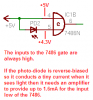
Thanks for all the problems  . I appreciate that but there is something missing from that schematic, i know. And i just talked to my grandfather about the thing that was missing from this circuit, so i will be redrwaing the circuit a little because i just learned a new thing ^^. Oh btw, that what i wan't to do is, that if the D1 photodiode goes blind, then the gate will output a high, so the transistor will trigger, but there is that problem, that if the D1 will see the light again, then the output of the logic will be low but i need the transistor to still be triggered. and for the second part of the schematic, the switch is allways on...
Oh and that thyristor is not the one on the picture, i just put it because of the symbol. the thyristors type is T122-25-12-4 (25 A, 1200V) I will be trying to make it a little more understandable. Oh and for the amplifiers for the photodiodes, maybe yeah maybe no, i'll see it when i will be experimenting with those photodiodes on a test board. Oh And not all my parts are old -.- just the thyristors, and maybe the photodiodes, i may be replaceing them with some new ones.
To Roff: Don't worry, you just shoot everything at me you have. I can manage.
Oh and i just wan't to do it with that logic gate because, i just wanna do it like that. Usually when i think on something, i make it, even if there is a faster/better/more simple way to do it.
EDIT: PE should be like ground, i put it for the symbol, i know that symbol a little more -.-. I will be tidying that schematic later so yeah i may be going to use the GND the program has.
. I appreciate that but there is something missing from that schematic, i know. And i just talked to my grandfather about the thing that was missing from this circuit, so i will be redrwaing the circuit a little because i just learned a new thing ^^. Oh btw, that what i wan't to do is, that if the D1 photodiode goes blind, then the gate will output a high, so the transistor will trigger, but there is that problem, that if the D1 will see the light again, then the output of the logic will be low but i need the transistor to still be triggered. and for the second part of the schematic, the switch is allways on... Oh and that thyristor is not the one on the picture, i just put it because of the symbol. the thyristors type is T122-25-12-4 (25 A, 1200V) I will be trying to make it a little more understandable. Oh and for the amplifiers for the photodiodes, maybe yeah maybe no, i'll see it when i will be experimenting with those photodiodes on a test board. Oh And not all my parts are old -.- just the thyristors, and maybe the photodiodes, i may be replaceing them with some new ones.
To Roff: Don't worry, you just shoot everything at me you have
. I can manage. Oh and i just wan't to do it with that logic gate because, i just wanna do it like that. Usually when i think on something, i make it, even if there is a faster/better/more simple way to do it.
EDIT: PE should be like ground, i put it for the symbol, i know that symbol a little more -.-. I will be tidying that schematic later so yeah i may be going to use the GND the program has.