Andy1845c
Active Member
First off, I think i'm getting to the end of the Inchworm woods!! haha Its working GREAT at the moment!
I have learned enough assembly to modify a program I found on the net to blink LEDs. I have made several patterns with 8 leds, but the program ends up being quite long. I need to see if there are simpler ways of doing things.
Question 1. How do you tell how big your program is? I assume I will get an error if I try to fit more then the PIC can hold?
2. After I program a PIC with the inchworm, will the PGD and PGC pins (RB6 and 7 on a 16F628) become avalible for general use when the PIC is in the project it will be controlling?
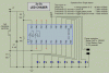
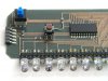
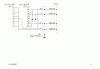
3. I want to select from 4-6 led patterns with a rotary switch. Is this possible/advisable with a single PIC? I assume I could use 4-6 seperate PICs, one for each pattern, but I am guessing thats not needed. Does anyone have a schematic or link to a similar project so I can get an idea on how this is done?
I have learned enough assembly to modify a program I found on the net to blink LEDs. I have made several patterns with 8 leds, but the program ends up being quite long. I need to see if there are simpler ways of doing things.
Question 1. How do you tell how big your program is? I assume I will get an error if I try to fit more then the PIC can hold?
2. After I program a PIC with the inchworm, will the PGD and PGC pins (RB6 and 7 on a 16F628) become avalible for general use when the PIC is in the project it will be controlling?
3. I want to select from 4-6 led patterns with a rotary switch. Is this possible/advisable with a single PIC? I assume I could use 4-6 seperate PICs, one for each pattern, but I am guessing thats not needed. Does anyone have a schematic or link to a similar project so I can get an idea on how this is done?