Continue to Site

Welcome to our site!

Electro Tech is an online community (with over 170,000 members) who enjoy talking about and building electronic circuits, projects and gadgets. To participate you need to register. Registration is free. Click here to register now.

  • Welcome to our site! Electro Tech is an online community (with over 170,000 members) who enjoy talking about and building electronic circuits, projects and gadgets. To participate you need to register. Registration is free. Click here to register now.

A circuit for a motion sensor receiver

Status
Not open for further replies.

stef10

New Member
Hey guys, im making a motion sensor which ignores ambient light sources and I have found a circuit which can receive the infrared beam which is transmitted at a certain frequency from a lm555 timer. But I would like to have someone to tell me in details how the receiver part works.

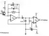
The circuit is down below

Thanks.
 

Attachments

  • Receiver..JPG
    Receiver..JPG
    21.5 KB · Views: 558
The first amp is tuned to have its best gain at a certain frequency, then it acts as a precision rectifier with D1, putting some negative volts into the capacitor. The second amp has a zero to negative 12 volt adjustment which is called a threshold. Anything less negative than the threshold voltage will not pass through the second amp. Anything more negative than the threshold voltage will be inverted and amplified to nearly 12 volts positive.
 
My teacher gave me some hints as to how I can tackle the 12 V, -12V problem, I have the circuit down below but I dont know how on earth you are supposed to get -12V out of it.
 

Attachments

  • split supply..JPG
    split supply..JPG
    16.6 KB · Views: 272
Status
Not open for further replies.

Latest threads

New Articles From Microcontroller Tips

Back
Top