Continue to Site

Welcome to our site!

Electro Tech is an online community (with over 170,000 members) who enjoy talking about and building electronic circuits, projects and gadgets. To participate you need to register. Registration is free. Click here to register now.

  • Welcome to our site! Electro Tech is an online community (with over 170,000 members) who enjoy talking about and building electronic circuits, projects and gadgets. To participate you need to register. Registration is free. Click here to register now.

868 MHz LPF

Status
Not open for further replies.

Mikebits

Well-Known Member
Greetings RF dudes. Using the normalized filter table (see table 1.), I worked out the numbers for a (5n) 868 MHz low pass filter (LPF). That was easy enough, but my results produce some values that are real small, (very small). I thought perhaps I could scale the load impedance (ZL) up or down, then match the scaled ZL with a balun. Using the equations for component values: L = (RL*Ln)/ω : C = Cn/(ω*RL). So you can see, if I scale ZL up I can have larger inductor values, but cap values will decrease, and vice a versa.

The values I have are 2.27 pf, 7.33 pf, and 14.8 nh. Now I can get these values but what I am concerned with is that the tolerances at smaller values can make a larger error where large values will be less critical as it pertains to tolerance. So I was just wondering if there are any tricks I can use to scale up my components? The reason I care is that I do not have a way to test the filter at 868 MHz, so what I am relying on is (by design) it should work.
Thanks

Table 1.
Order RS C1 L2 C3 L4 C5 L6 C7
a1 a2 a3 a4 a5 a6 a7
1 1.0 2.0000
2 1.0 1.4142 1.4142
3 1.0 1.0000 2.0000 1.0000
4 1.0 0.7654 1.8478 1.8478 0.7654
5 1.0 0.6180 1.6180 2.0000 1.6180 0.6180
6 1.0 0.5176 1.4142 1.9319 1.9319 1.4142 0.5176
7 1.0 0.4450 1.2470 1.8019 2.0000 1.8019 1.2470 0.4450
 
Essentially by that high a frequency it's more plumbing than electronics :D

Layout is absolutely critical, and it's usual to use lecher lines rather than actual coils - possibly etched directly in a PCB (assuming you're using a PCB?).
 
Thanks Nigel, your probably right. As far as doing planar component design, I think that is a bit beyond my skill level. The math involved makes me run into the night screaming...
Maybe I can find an off the shelf solution. The purpose is to get rid of some distortion products of a signal source, so the 2nd 3rd harmonics are pretty far out so filter does not have to be tight.

Thanks
 
Back when I worked in the real world, I was able to get samples for anything I needed just by saying who I worked for. Now the sales people are like "erm, right buddy, we will have that to you asap. click..." I can picture their look on the phone. :rolleyes:
 
Speaking of planar microstrip components (I think that is what you call em), Does anyone know of any good/practical text, (online or book) on the subject.
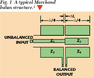
https://www.microwavejournal.com/articles/3265-design-of-a-planar-microstrip-balun-at-s-band

132fig01.jpg


I have a Hard Copy of Microwave engineering, but most of it goes over my head due to the math (I have discalculia or something :)
Example screen shot of book contents.
Math.JPG
 
Last edited:
Essentially by that high a frequency it's more plumbing than electronics :D

Layout is absolutely critical, and it's usual to use lecher lines rather than actual coils - possibly etched directly in a PCB (assuming you're using a PCB?).

I did not know what a Lecher line was, I had to Google it. That is really old-school:eek:
Back when I was in Navy we had a SWR instrument used for tuning waveguide, I guess it was a Lecher line device, I just did not know the name. We called it an AN-SMQ something or other, it was just a hunk of wave guide with a thing that slid along a slot in the waveguide on two rods. But that was back in 1979 :arghh:

SWR.PNG
 
I just did not know the name.

The word you are looking for is "Slotted Line".

They were (are still ?) made in waveguide form and coaxial line form.
A probe measures the electric field strength inside the waveguide or coax.

JimB
 
I did not know what a Lecher line was, I had to Google it. That is really old-school:eek:

I'm quite amazed I spelt it correctly :D

Basically UHF tuners in TV's used lecher lines, as the frequency is too high for coiled inductors.

You also used them for the 70cm amateur band as well - although as it's just below UHF TV, you could just about get away with coils.
 
Essentially by that high a frequency it's more plumbing than electronics :D

Layout is absolutely critical, and it's usual to use lecher lines rather than actual coils - possibly etched directly in a PCB (assuming you're using a PCB?).

While Nigel makes a good point, I wanted to add my own experience in this area. I've done a lot of design from 400 MHz to 6000 MHz and can attest that lumped reactances (ie. discrete inductors and capacitors) are much more convenient and practical to use at 900 MHz when compared to distributed (transmission line) circuits. However, as Nigel teaches, layout is supremely critical and the smaller surface mount components are essential. By smaller, I mean 0402 inductors and capacitors and while 0603 will work ok, why bother as it is only slightly harder to work with 0402 than with 0603 and stray reactances are less significant with the smaller parts. Once you become familiar with how "long" is too long a pcb trace at these frequencies, it all becomes fairly easy to successfully build your circuit. Often, once you have your pcb in front of you, a bit of tuning is necessary to optimize a circuit and it is very easy to swap from one value of inductor or capacitor to the next.

In designing commercial equipment the point where the advantages of using distributed reactances (transmission lines instead of discrete or lumped capacitors and inductors) exceeds those of using lumped elements is rather vague but in my experience it might be around 4000 MHz. This depends on your priorities and can vary from 1500 MHz o greater than 6000 MHz. Much of my last five years in design has been in the 5000 to 6000 MHz range and we still use lumped elements in most cases for interstage impedance matching, although it can be tricky. At these frequencies, for example, the length of an 0201-size chip inductor has to be compensated for when doing a series matching inductance. I have also found that, at these frequencies, it is best to purchase the lowest tolerance parts.

One benefit of using lumped elements vs distributed elements is that you can finish your circuit and begin production more quickly. You can also get away with lower performance pcb substrates too. Disadvantages include the problem of variation or tolerances, where pcb traces may be better controlled than discrete component values. PCB area, and so overall circuit size, will be larger with distributed elements. In commercial products, and especially consumer items, product size and time-to-market are very important so lumped elements are popular in, for example, mobile phones and wifi gear even though these operate at 1.7 to 6 GHz. Admittedly, these high volume consumer goods don't use much pcb copper at RF anymore as almost all the RF circuits are within one or very few RF ICs.
 
That ceramic 805 sized filter is a multilayer filter like the MLCC ones MOT designed 17 yrs ago for their Iridium Satphones for which I designed the VNA automated calibration of their LNA and Tx/Rx switches with o 0.1dB accuracy of VNA and test jig up to 5GHz.

When I worked with RF Engineers at another place in the 928MHz ISM band 8kHz BW, they used custom SAW filters for BPF and discrete widerband LPF HPF with 603 discrete parts and microstrip on GETEK flex laminate. (thin but lower (10% of) loss tangent of FR4 for 10% more, but much cheaper than PTFE. <0.5pF and 0.5nH was doable with tinned brass shields to cut down on stray crosstalk and emissions. PAtch Antenna return loss was custom and had a return loss> 15dB.

In the old payTV days (early 80's) 1/4 wave stubs were commonly used to notch out the jammed carrier between Luma and Audio for Channel 22 with good results Q> 200, Helical air coils with precision symmetry could get higher Q, but they were a tad long than the 805 ceramic filter. ;) From looking at the 2f (-30dB) and 3f (-40dB) I would estimate they have a 4th order 1/2dB linear phase filter. For 603 caps 0.1pF COG is doable, and etched inductors are done with impedance matching to get a high enough SRF unless it just for power decoupling. It depends on your overall requirements for s-parms both inband bandpass and outer bandstop specs for type of filter.

Did you notice Johanson has software for you? https://www.johansontechnology.com/software
I remember using their excellent coaxial multiturn trimmer caps in the 70's. ah those were the days..my friend ...∞

Tony

p.s. **broken link removed**
**broken link removed**
 
Last edited:
Nice, I just downloaded that software from JT. Thanks
 
Last edited:
For only $25,000.00 you can get the whole MoM package :)
 
The further I dig, and the more I read on Microstrip, parasitics, lumped and distributed elements, the more I realize just how ignorant I am. :) I find this whole topic and aspect of RF design extremely fascinating.
As Howard Johnson says in his book, "High Speed Digital Design";
"It is not black magic, it just seems that way" Mr. Johnson goes on in this book to dispel the myth about RF and High speed design as magic.
 
Last edited:
While Nigel makes a good point, I wanted to add my own experience in this area. I've done a lot of design from 400 MHz to 6000 MHz and can attest that lumped reactances (ie. discrete inductors and capacitors) are much more convenient and practical to use at 900 MHz when compared to distributed (transmission line) circuits. However, as Nigel teaches, layout is supremely critical and the smaller surface mount components are essential. By smaller, I mean 0402 inductors and capacitors and while 0603 will work ok, why bother as it is only slightly harder to work with 0402 than with 0603 and stray reactances are less significant with the smaller parts. Once you become familiar with how "long" is too long a pcb trace at these frequencies, it all becomes fairly easy to successfully build your circuit. Often, once you have your pcb in front of you, a bit of tuning is necessary to optimize a circuit and it is very easy to swap from one value of inductor or capacitor to the next.

In designing commercial equipment the point where the advantages of using distributed reactances (transmission lines instead of discrete or lumped capacitors and inductors) exceeds those of using lumped elements is rather vague but in my experience it might be around 4000 MHz. This depends on your priorities and can vary from 1500 MHz o greater than 6000 MHz. Much of my last five years in design has been in the 5000 to 6000 MHz range and we still use lumped elements in most cases for interstage impedance matching, although it can be tricky. At these frequencies, for example, the length of an 0201-size chip inductor has to be compensated for when doing a series matching inductance. I have also found that, at these frequencies, it is best to purchase the lowest tolerance parts.

One benefit of using lumped elements vs distributed elements is that you can finish your circuit and begin production more quickly. You can also get away with lower performance pcb substrates too. Disadvantages include the problem of variation or tolerances, where pcb traces may be better controlled than discrete component values. PCB area, and so overall circuit size, will be larger with distributed elements. In commercial products, and especially consumer items, product size and time-to-market are very important so lumped elements are popular in, for example, mobile phones and wifi gear even though these operate at 1.7 to 6 GHz. Admittedly, these high volume consumer goods don't use much pcb copper at RF anymore as almost all the RF circuits are within one or very few RF ICs.

As always I look forward to your input Ron. Very insightful, educational, and aids in furthering my understanding of RF design, and you as well Mr. Stewart :)
 
Status
Not open for further replies.

Latest threads

New Articles From Microcontroller Tips

Back
Top