Continue to Site

Welcome to our site!

Electro Tech is an online community (with over 170,000 members) who enjoy talking about and building electronic circuits, projects and gadgets. To participate you need to register. Registration is free. Click here to register now.

  • Welcome to our site! Electro Tech is an online community (with over 170,000 members) who enjoy talking about and building electronic circuits, projects and gadgets. To participate you need to register. Registration is free. Click here to register now.

8 LED Light Bar using 74HC164

Status
Not open for further replies.

ImWolf

New Member
Hello All.....

I'm trying to re-create a circuit I recently built using an AMV to clock a 4017, with Thyristors to latch 10 LED's through each cycle, ending up with a "light bar" of sorts. Here's a short video of the exact effect I'm after.....

https://www.youtube.com/watch?v=o3yrkszC748

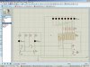
This circuit will eventually be used for model kit lighting, and although I was able to fit the 52 components onto a 1.6" x 2.4" board, it's still a bit too big to fit inside my model. Someone suggested I could do the same job at 8 LED's using a 74HC164, so I bought some of those but haven't been able to match my previous output.

I'm using a 6V supply. I started out with the same AMV as the previous circuit, but thought I'd try using a 3909 for a clock to get the size down even smaller. This just left me with an LED blinking, then 2, then 3, etc..... a cool effect actually, but not what I'm after.

With the AMV clock however (or the 3909), I'm seeing only 7 of the 8 LED's light and latch (seems like the first two don't really turn off fully), and after a random number of cycles it locks up and all 7 LED's remain lit. (or blinking).

I have zero formal training in electronics, and needed some help to complete the previous circuit. If anyone is interested in reading through that process and how I got to this point you can check out the following.....

https://forum.allaboutcircuits.com/showthread.php?t=85466

Thanks for any assistance.....
Wolf
 
I'm seeing only 7 of the 8 LED's light and latch (seems like the first two don't really turn off fully), and after a random number of cycles it locks up and all 7 LED's remain lit. (or blinking).
Perhaps the poor little '164 is overheating. What is the current through each LED?
I think an LM3914 might be a better IC for your purpose.
 
Perhaps the poor little '164 is overheating. What is the current through each LED?
I think an LM3914 might be a better IC for your purpose.

Hi Alec.... I've seen different datasheets on the 164 which put the max. V input at either 6V or 7V. Even though my power source is actually two bridged 3V watch batteries, I added a IN4001 diode at the Vcc pin to drop the input closer to 5V.

Perhaps I should have included a picture? I'll attach one of the many schematics I've tried to get this thing working and repeating.

I'm thinking that the reason LED #8 isn't firing has everything to do with the fact that I'm also re-directing the last output back to the serial inputs and the reset in different attempts to short/reset/restart the cycle..... but I can't get it behaving properly. My attempts have included using NPN and PNP transistors in various configurations, and putting capacitors along the way to stall the current and allow the last LED to work with the current it should be receiving for enough time to fire. When I remove the "re-direct" jumper from the last pin-out then the 8th LED does fire and the cycle runs once only.

The LED's I've chosen are 3mm green round rated at 3.0-3.2V x 20mA. I'm using 470ohm resistors between the pin-outs and the LED's.

And yes Alec, having now read a lot of forum posts on sequencing LED's I am interested in playing with LM3914 at some point, but for now I'd rather see if I can get a working circuit with the materials I've already bought.

Wolf
 

Attachments

  • 74hc164X.jpg
    74hc164X.jpg
    270.2 KB · Views: 2,074
Last edited:
hi wolf,

This TPIC6595 shift register is a power driver.

E
 

Attachments

  • TPIC6595.pdf
    185.1 KB · Views: 383
may be you need some thing like this circuit....74164.JPG
 
may be you need some thing like this circuit....View attachment 74646

Thanks for the input Ikelectro....

I assume the cathodes of your LED's go to GND even though you didn't draw that out...

Also, I had to look up the symbol marked "U1A" (I'm very new to this stuff) and I don't have anything like an inverter in my stash to test your design. Can I make an inverter with discrete components?

Thanks,
Wolf

yes it should be grounded....... i had used just logic indicator (instead of LED< you have to use LED) in the schema for reducing wiring..... ...

yes you can make a inverter with 1 transistor and 2 resistor .....Inverter with trnsistor.JPG
 
Hi Eric......
Not sure what a TPIC6595 is..... wasn't able to open the PDF for some reason....

Thanks just the same.... :b
Wolf
Hi,

I have done a downloaded the pdf , I can open it it ok?

Posted the first page for you.
E.
 

Attachments

  • AAesp01.gif
    AAesp01.gif
    90.5 KB · Views: 434
@Eric: My Adobe was eventually able to open the PDF without errors..... I'm still hoping to make the materials on hand work for me b4 experimenting with new devices. Thanks.... :b

@Ikelectro: Thanks for adding that second diagram of the inverter. When I put the two pieces of your puzzle together it looks identical to a schematic another fellow had suggested and which I'm 99% sure I had tried..... but tried again last night.

In the Proteus 8 Demo software I D/L the circuit sequentially fires and latches all 8 LED's, then it sequentially turns them off one by one to complete a cycle. With hardware on my BB however, I'm not getting that behavior at all. (This is not the first time I've seen things work in software but not hardware, or vice-verse).

I get the feeling that I'm making a very basic mistake somewhere on the BB (which folks like you would see instantly), but even after I look at it 100 times (which I have) I just don't see the problem.

Perhaps I need to add a toilet flusher handle? :b

Thanks guys.... I'll keep playing with it....
Wolf
 
Hi Wolf, let me assume that you have placed the hardware as the circuit i had supplied to you... So now we can also assume that your Vcc is 5.5V or 5V. And you should get this volt on 74164's pin no. 2,9 and 14..... and pin 7 is gnd..... and you have clock pulses on the pin no. 8... just make sure these things...... hope you are using a multimeter to find that out...
thanks....
 
Update:

Made some progress of sorts..... started playing with my multimeter (MM) and a variable power supply (VPS) which led me to a problem.

Started by just testing the battery pack output (which I hadn't done b4) and the MM said it was putting out 5.5V. (not sure if this is normal for two bridged 3V batteries?) Then I connected the leads to the BB and tested the voltage at the next pin holes..... MM said 2.9V. "That's strange" I thought.... would the components on the circuit be causing this for some reason?

So I repeated the experiment with my VPS set at 5.5V..... (MM said 5.63). Used it to power the circuit and again tested voltage at the next pin holes..... MM said 4.9V..... exactly what it should be after going across a single IN4001 diode.

The circuit was still behaving erratic..... doing all kinds of stuff. So I started turning down the VPS and when I got close to 4.5V everything suddenly worked fine. (The 8 LED's latched one by one, and then shut off one by one.) At 4V the LED's that still did light where barely on. I guess the 74HC164 is very finicky about how much juice you pump into it?

So, even though the batteries had not seen that much use, I inserted new ones..... MM said output was now 6.7V. Attached it to the BB and had to go thru 2 diodes b4 the circuit functioned properly again. I left it running for 100 minutes and then decided to check what the voltage was actually running the board.

While I was attaching the MM the circuit suddenly froze up with 7 LED's lit..... Did I do that?

Went ahead and checked the next pin holes and MM said there was 3.1V going into the BB. Checked the battery pack and MM said output was now down to 5.6V. Plugged the battery pack back into the BB by-passing one diode and the circuit began working as b4. MM reports fluctuating between 3.6V and 4.2V going into the board.

These batteries are rated at 220mAh..... if I have to change batteries every 2 hours that's not cool. Kinda hard to by-pass a diode once the finished circuit board is soldered too.

I'm using pretty much the exact circuit that Ikelectro offered up above, and I'm using a 3909 to clock the 74164..... I'm open to suggestions on how to improve battery life and stability.
 
These batteries are rated at 220mAh
That rating applies only under specific (low current) discharge conditions (check the datasheet). Your average current drain is ~4mA x 8 / 2 = 16mA LED current + 6mA inverter current = 22mA so battery life will be reduced considerably.
Watch batteries are not designed for high currents. Their internal resistance drops the voltage supplied to your circuit, which is probably why you are getting erratic results.
If you increase the value of both resistors in the inverter (to, say, ~33k ) you can reduce the inverter current to next to nothing.

Edit: BTW, the LM3909 uses a fair bit of current. There are lower current (and much cheaper) alternatives.
A way to reduce current dramatically would be to change the light bar to a 'one LED at a time' display.
 
Last edited:
Thanks for that info Alec.....

I switched to using the 3909 to reduce the size of the circuit. If I go back to using an AMV with two transistors would that be less current usage? (The AMV also uses two 1K, two 10K, and a pair of 10uF capacitors.)

The highest resistors I have on hand are 10K...... of which there is one being used in the current inverter along with a 1K. Until I go shopping I guess I can replace the 1K with another 10K and see if this gives me any better battery life.

BTW, the circuit I originally wanted would turn all the LED's off simultaneously and then restart the cycle...... couldn't make that happen so far with the 74164 though.

Wolf
 
BTW, the circuit I originally wanted would turn all the LED's off simultaneously and then restart the cycle...... couldn't make that happen so far with the 74164 though.
This will do it....
BarLightChaser.gif

Edit: You could use 10k instead of 33k in the above circuit (at the expense of greater current).
 
To reduce the component count you could use this circuit:
BarLightChaser2.gif
The 74HC132 is used to generate the clock signal as well as to do the logic for resetting the LED sequence.
 
@Ikelectro: Sorry for not responding to your most recent post sooner friend.... did not see it or the WebGremlins were busy..... I'm getting the same voltage at pins 2,9, and 14 as the meter reads at entry to the breadboard. And yes, I'm using the correct pins for clock and ground.

@Alec: Just tested your "all off" schematic...... works great! Thank you Sir.... :b I don't have any of the HC132's, so that will have to be tried another day. I noticed in that (2nd) schematic you posted that the resistors are at the cathode end of the LED's.... I thought they should always be at the anode?

@All: More strange battery behavior afoot...... As I posted recently I had installed new batteries and the circuit only ran for 100 minutes. What I did not post is that I then by-passed one of the diodes and the circuit ran for another 45 minutes. Then I by-passed both diodes and the circuit ran for a last 15 minutes. In all three cases voltage tested at the BB entry had dropped to 3.1V.

I left it laying there and turned it back on this evening (about 24 hours later) and the circuit began running fine.... which surprised me since I thought those batteries were toast. Voltage at the BB was back up (fluctuating) between 4V & 5V, and testing the battery pack alone was back up to 5.85V. (previously 5.5V).

Are these batteries draining fast, or over heating?

Thanks for all the help folks....
Wolf
 
works great!
Good to know.
I noticed in that (2nd) schematic you posted that the resistors are at the cathode end of the LED's.... I thought they should always be at the anode?
It makes no difference which end; all that matters is that they are in series with their respective diodes.
Are these batteries draining fast, or over heating?
They're draining fast and probably warming slightly. After a heavy discharge they will recover partly if 'rested' for a while, as you found.
BTW, as you want compactness are you using surface mount components, including SOIC versions of the ICs?
 
Alec....

I just leaned how to operate an LED a few months ago and have not messed around with any surface mount components. :b

On a surface mount circuit, I would imagine all the connections have to be made on the component side.... thus entailing more careful soldering?


Wolf
 
Status
Not open for further replies.

New Articles From Microcontroller Tips

Back
Top