Continue to Site

Welcome to our site!

Electro Tech is an online community (with over 170,000 members) who enjoy talking about and building electronic circuits, projects and gadgets. To participate you need to register. Registration is free. Click here to register now.

  • Welcome to our site! Electro Tech is an online community (with over 170,000 members) who enjoy talking about and building electronic circuits, projects and gadgets. To participate you need to register. Registration is free. Click here to register now.

8 bit binary of ADC0804 to decimal view in & segment.

Status
Not open for further replies.

ikelectro

Member
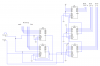
I'm using a ADC0804 and it has 8 bit binary out out.
I want to decode this 8 bit binary into three 7 segment display(as 11111111=255). what digital IC should I use in that case. i have been worked with 4510,4511, 4029.
plz friends help me out. as i dnt know microcontroller i have to use digital ics. plz guys tell me something what should I do.
 
Preset the binary output word into an 8-bit binary counter. Next, simultaneously clock down the binary counter and clock up a cascaded series of three decade counters until the binary counter reaches the zero count. Use the preset operation to clear (reset) the decade counters to zero. Use BCD to 7 seg decoder chips between the decade counter outputs and the 7 segment displays. The CD4026 combines the decade counter and 7 seg decoder, if desired.

Alternatively, you can program a memory chip(s), whereby the 8-bit binary word addresses the memory to produce a bcd or 7 seg output from the memory.
 
Last edited:
can you give me circuit or image??? that will be more helpfull to understand.
I have 4026, 4510 ICs. or you can help with suggestion which IC should I use.
 
Last edited:
This provides the Binary to BCD conversion. Use BCD to 7-seg decoders like 4543, or 4511 for the displays.
 

Attachments

  • bin to bcd convert electro tech.png
    bin to bcd convert electro tech.png
    41.4 KB · Views: 8,322
Thanks a lot. i'll do it. thanks once again.
 
This provides the Binary to BCD conversion. Use BCD to 7-seg decoders like 4543, or 4511 for the displays.
Why didn't you use the CD4026, as you mentioned in your previous post, to eliminate the need for a separate BCD to 7-segment decoder? :confused:
 
Why didn't you use the CD4026, as you mentioned in your previous post, to eliminate the need for a separate BCD to 7-segment decoder?

I don't have the model for the CD4026 and I was feeling too lazy to draw them in.

Edit: Okay, so it wasn't so much work afterall. Ta-da! I even threw an example of using the 4033 in place of one of the counter/decoders instead of the 4026
 

Attachments

  • BIN TO BCD ELECTO TECH DWG.png
    199.3 KB · Views: 4,625
Last edited:
I don't have the model for the CD4026 and I was feeling too lazy to draw them in.

Edit: Okay, so it wasn't so much work afterall. Ta-da! I even threw an example of using the 4033 in place of one of the counter/decoders instead of the 4026


1. Can i use 4510 instead of 4526. because 4510 can make. down or up counting. If yes then what'll be
the circuit.?
2. What should be the clock frequency and converter frequency???
 
Last edited:
**broken link removed**
i use two 4510 and three 4026....
ADC 0804 out puts are happening. but display always showing me 000.
what,ll be clock and converter frequency????
 
The clock and convert frequency determine the speed of the display update.
The convert loads the new binary value into the counter.
The clock frequency then determines how fast the new binary value is converted to BCD.
 
**broken link removed**
i use two 4510 and three 4026....
ADC 0804 out puts are happening. but display always showing me 000.
what,ll be clock and converter frequency????

Sorry. I can't bring up your attachment. I get an error. The 4510 are BCD counters and so they cannot be used in place of the 4526 binary counters.

The clock frequency can be anything up to the max clock frequency of the counters (2.5 MHz for the 4026/4033; 5 MHz for the 4510/4526). If the clock is 256 Hz, it can take as long as 1 second for the conversion to take place; 2,560 Hz, 0.1 second; 25,600 Hz, then 0.01 second to convert, and so on. The faster the clock frequency the faster the conversion.

The convert pulse must be at least 200 ns wide. When the convert pulse goes high, the binary counters load and the BCD counters reset and are held that way until the pulse goes low. When the pulse goes low conversion begins at the next clock pulse and continues until finished.
ok, i understand... then i have to use 4526 instead of 4510. but can I use all decoder 4026( in your circuit there is a 4033 and two 4026. is there any special reason for that combination of 4033 and 4026? is that possible to use all decoder 4026?)?
 
ok, i understand... then i have to use 4526 instead of 4510. but can I use all decoder 4026( in your circuit there is a 4033 and two 4026. is there any special reason for that combination of 4033 and 4026? is that possible to use all decoder 4026?)?

You can use all 4026. I only put the one 4033 in there to show how a 4033 would be connected.
 
You can use all 4026. I only put the one 4033 in there to show how a 4033 would be connected.

ok. thanks a lot. and what should i do with the converter speed. pardon my unknownness.!!!!;)
 
I'm asking about the second circuit that you posted yesterday. there were clock and converter. you told me i can give 256hrtz to the clock. i'm asking what should i do with the converter.
 
Last edited:
It depends on how often and when you want to perform a Binary to BCD conversion. The convert input is simply the pulse that loads the bin-BCD converter with the 8-bit binary word and then starts the bin-BCD conversion. Anything can be used to pulse the convert input as long as it allows at least 256 pulses (preferably 2560 pulses or more) of the clock input for the conversion to complete before pulsing again for the next conversion.

I'm giving around 9Khz to the converter. is that ok?
 
View attachment 66788
IN THIS, what no. of pin is CE, DE, EO and 2C.plz reply as soon as possible.!!thanks.
 
IN THIS, what no. of pin is CE, DE, EO and 2C.plz reply as soon as possible.!!thanks.
CE = pin 2
DE = pin 3
EO = pin 4 (unused)
2C = pin 14 (unused)

I'm giving around 9Khz to the converter. is that ok?

At 9 KHz it will take about 28 ms for the BCD display to count to the final value (do the bin-to-BCD conversion). That's pretty quick as far as the human eye can notice.
 
Last edited:
Status
Not open for further replies.

Latest threads

New Articles From Microcontroller Tips

Back
Top