Continue to Site

Welcome to our site!

Electro Tech is an online community (with over 170,000 members) who enjoy talking about and building electronic circuits, projects and gadgets. To participate you need to register. Registration is free. Click here to register now.

  • Welcome to our site! Electro Tech is an online community (with over 170,000 members) who enjoy talking about and building electronic circuits, projects and gadgets. To participate you need to register. Registration is free. Click here to register now.

7segment display

Status
Not open for further replies.

tzk1994

New Member
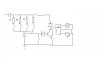
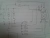
I have this project that requires me to create a RC timer circuit. i have built the circuit using a selector switch in which when R1 is connected to the 100uF capacitor a time delay of 1 min is created. when R2 is connected a time delay of 2min is created. and now i want to add in a seven segment display. i have a common cathode seven segment display. how shld i connect it so that whenever i change to a for example from R1 to R2 the seven segment display will show number 1 changing to 2? I need the circuit diagram.
And one more thing. after timing the capacitor gets charged up. and after everytime it is used, users have to press the switch parallel to the capacitor to drain the excessive charges in the capacitor before using it the next time. i heard we could use a relay to replace the switch. How then can we do it? i am using 11.5 V
 

Attachments

  • untitled.JPG
    untitled.JPG
    15.1 KB · Views: 275
As drawn the circuit relay won't do anything. You want that snubber diode in parallel (not series) with your relay coil. Same polarity but parallel not series as you have it drawn.

If you want to include the 7 Segment LED you will need to use a Display LED decoder like a 7447 for example. 7447 Data Sheet Link.

Ron
 
my circuit is roughly like that. i am not sure what is it like. the part with the diode and relay to control the bulb is just a rough drawing. i just need to know how to connect the 7 segment display R1 R2 etc and i cannot use ICs.
i know how to test for which one is a b c d e f g. i am just unsure how to connect it to the resistors
 
Last edited:
OK, attached is a 7 segment LED display in the rough with resistors for the segments. If you wanted to display a 1 then segments B and C would be taken high through their respective resistors. If you want to display a 2 then segments A, B, G, E, and D would be held high through their resistors. The problem is you can't for example tie B & C together easily for a 1 then tie A, B, G, E, and D together for a 2 very easily. This is why 7 segment displays use decoders like the 7447 I linked to. Then it would be real simple to render a 1 & 2.

Best of luck with some form of switching matrix.

Ron
 

Attachments

  • 7 Seg Display.gif
    7 Seg Display.gif
    3.5 KB · Views: 298
You can use diodes in series with each common wire to isolate the signal for 1 from the signal for 2. Thus, for example, if you use segments B & C for 1 and A,B,G,E, and D for 2 then you put a diode in the line that goes to segment B for 1 and a diode that goes to segment B for 2.
 
is it something like that? for 1 and 2. i will be using 220 resistors. and the top part of the seven segment display, the middle connection stick does it have to be connected to the power supply? because it is common cathode. in ron's picture it does not show the seven segment connected to any power supply
 

Attachments

  • IMG129.jpg
    IMG129.jpg
    188.5 KB · Views: 357
Status
Not open for further replies.

Latest threads

New Articles From Microcontroller Tips

Back
Top