Continue to Site

Welcome to our site!

Electro Tech is an online community (with over 170,000 members) who enjoy talking about and building electronic circuits, projects and gadgets. To participate you need to register. Registration is free. Click here to register now.

  • Welcome to our site! Electro Tech is an online community (with over 170,000 members) who enjoy talking about and building electronic circuits, projects and gadgets. To participate you need to register. Registration is free. Click here to register now.

7805 reg question

Status
Not open for further replies.

ShawnR

Member
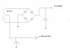
I rebuilt my power supply the last few weeks. I had a couple of LED panel meters (Volt and Ammeter) and thought I would convert my old single output lm350T regulated supply to a 3 output (5,12, var) supply. Transformer is a 26.2 Center tapped. I used the full windings and feed three regs (7805, 7812, 350K) after the large (enough) bridge rectifier. Variable works fine. 7812 output appears OK

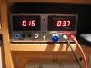
Problem is that the 7805, supplies the +5 for the digital meters. This voltmeter is to display the variable output value. With the voltmeter connected, it draws about 40 mA. It causes the 7805 to immediately shut down to ~2 volts, thus wreaking havoc on the meter. I know the meter is OK as I temporarily connected it to the var output at 5 volts and it is fine. Anyone have experience with this? I thought I popped the 7805 so replaced it but same thing next time. The input voltage is quite high....38 volts after rectification and filtering, no load, but at such a low current draw, power dissipation in the 7805 is just over 1 watt and the shut down is immediate so I do not think it is a heat issue.

Any suggestions? Input just too high?
 
Last edited:
Some meters can and some can not measure their own supply voltage with the issue being common or ground. If you simply power the meter without the meter inputs connected does it work?

Many meters, especially lower cost panel meters cannot measure a signal referenced to their own power supply 0V. When it comes to multiple meters do not connect more than one meter to the same power supply if the meters cannot use the same signal ground.

I am not saying this is your problem, merely that it could be. Also, following your post my read is that your input to the 7805 is pretty high. I am assuming 26.2 VAC rectified and passed to a filter cap. That should yield around 37 volts less diode drops. Really high for a lowly 7805 regulator. That assumes I read what you posted correctly.

Ron
 
Hi Ron

Thanks for the fast reply. I purchased the meters from ebay about 10 years ago and no longer have the documentation on them, so not sure about whether they can monitor their own ground referenced source. I will experiment some more. I was wondering if the input voltage was just too high for the 7805?

Maybe my thoughts of a 3 output power supply with one transformer were a little lofty..;-) Or I suppose I could use a power transistor to reduce the input to the 7805..mmmmmm?
 
The 7805 is likely fine. I agree with Ron that the problem is probably the meter.

Another thought. To minimize power dissipation for the fixed 5V and 12V outputs, you can use the transformer center-tap to get a 13.1V full-wave rectified signal. Just add a filter cap to the center tap and you will get an output of about 16-17V DC. This works because the bridge performs double duty, acting as a two-diode full-wave rectifier for the center tap and well as a 4-diode full-wave bridge for the two main outputs.
 
Last edited:
Thanks Crutschow

I briefly considered using the center tap but thought I would need to move ground or cause a short. Attached is a schematic....would this be correct? That would be a much better way to go, if I understand correctly.

I do want to be able to use all three outputs together ie a common ground for the 5,12 and variable.
 

Attachments

  • Triple PS.jpg
    Triple PS.jpg
    18.9 KB · Views: 166
Yes, that circuit is correct. If you look at the current flow you will see that the two grounded rectifiers in the bridge act as a full-wave rectifier for the center tap. It's opposite of the way most full-wave rectifiers are connected, with the center-tap grounded and the rectifiers on the two end connections, but it works just the same.

You only have a shorting problem if you try to use two bridge rectifiers off winding taps that are not isolated.
 
Last edited:
I finished up the project a couple of weeks ago and wanted to say Thanks to the replies (repliers? :) )

The LED meters did end up working out fine in the end. I have had them (and this project) on my mind for a long time (~10 years...) and finally got around to it.

Using the Center tap worked perfect. I have not tested it too see how much current I can draw from the 7805 and 7812 but it should be fine. I have a small heatsink on them.

This project was mainly about the power supply but climbed up the list as I wanted to practice making a printed circuit board before moving on to larger projects so all in all, worked out well.

Thanks

Cheers,

Shawn
 

Attachments

  • IMG_3168.JPG
    IMG_3168.JPG
    592.7 KB · Views: 163
Status
Not open for further replies.

Latest threads

New Articles From Microcontroller Tips

Back
Top