Continue to Site

Welcome to our site!

Electro Tech is an online community (with over 170,000 members) who enjoy talking about and building electronic circuits, projects and gadgets. To participate you need to register. Registration is free. Click here to register now.

  • Welcome to our site! Electro Tech is an online community (with over 170,000 members) who enjoy talking about and building electronic circuits, projects and gadgets. To participate you need to register. Registration is free. Click here to register now.

74LS47 w/ 7-seg display latching up?

Status
Not open for further replies.
Hey there,

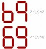
I'm building an experimental 1-digit counter w/ 74LS90, but there's a small problem: I could only hook it up to show BCDs successfully, but not when I connect it with the 74LS47.

The display latches up with gibberish when I connect it to +5V and worse, it didn't budge when the counter is counting.

What could have happened to the decoder? :D
 
Can you show your circuit? Are you aware the 7447 is open collector active low output so you need to make sure your LEDS or display anodes are tied to a logic 1 level and your 7447 drives the cathodes. Without a diagram of your circuit, I really can't say much...
 
Can you show your circuit? Are you aware the 7447 is open collector active low output so you need to make sure your LEDS or display anodes are tied to a logic 1 level and your 7447 drives the cathodes. Without a diagram of your circuit, I really can't say much...

Ok, here's the circuit... Maybe I might have left something here! :D
 

Attachments

  • untitledm.GIF
    untitledm.GIF
    8.4 KB · Views: 613
So the etchersketch is still around :) For starters you need current limit resistors between the 7447 and the display.
 
If you want to make nice schematic drawing, might I suggest this free download, called Eagle.


I only say this because your drawing is, how do I put this...
 
Last edited:
Ok, here's the circuit... Maybe I might have left something here! :D

Attached is a little better drawn circuit, also done with paint, by the way.

It uses the 7448 and drives a common cathode, but the connections are the same. What are you using for clock, and are you using by-pass capacitors across the power supply? The latter is very important with counter circuits.
 

Attachments

  • usual counter.GIF
    usual counter.GIF
    7.3 KB · Views: 594
In reference to original circuit.
You need to connect pin 1 to pin 12 of your 7490.

Oh, just noticed. Allvol circuits shows that. never mind...
 
Last edited:
Attached is a little better drawn circuit, also done with paint, by the way.

It uses the 7448 and drives a common cathode, but the connections are the same. What are you using for clock, and are you using by-pass capacitors across the power supply? The latter is very important with counter circuits.

Ok, got it. But there's another weird problem here - when I add another digit there (counting more than 10, or 10s), the 2nd digit seems to be frizzled. The strange thing is, when I checked the BCD, they are correct.

And the voltage regulators are with the capacitors as well! :)
 
Ok, got it. But there's another weird problem here - when I add another digit there (counting more than 10, or 10s), the 2nd digit seems to be frizzled. The strange thing is, when I checked the BCD, they are correct.

And the voltage regulators are with the capacitors as well! :)

Get 1 digit working first. You need to tie pin 1 to 12 of your 7490 or it won't work right. Add the current limit resistors as well.
I am not sure how you determined BCD worked correctly, but I suspect it did not other than blinky leds.
 
Get 1 digit working first. You need to tie pin 1 to 12 of your 7490 or it won't work right. Add the current limit resistors as well.
I am not sure how you determined BCD worked correctly, but I suspect it did not other than blinky leds.

The first digit is working now after i fixed it. The 2nd one isn't - it counts from 1, (frizzled 2), 3, (frizzled 4), 5 and back to 0 (i make a simple egg timer - so 60 seconds there). And the resistors are added as well. The BCD has been double-checked and it's correct. Only thing left is the decoder for the 2nd digit. haha. :)
 
Last edited:
Ok, got it. But there's another weird problem here - when I add another digit there (counting more than 10, or 10s), the 2nd digit seems to be frizzled. The strange thing is, when I checked the BCD, they are correct.

And the voltage regulators are with the capacitors as well! :)

Note that the 7447 (48) and seven segment LED are a pair. If you add another digit (LED), you must add another driver as well.

And by by-pass caps, we refer to caps placed between the Vdd pin of the 7490 and ground, for example. It absorbs any spikes that might appear in the power circuit, which the counter may confuse with clock pulses
 
74ls47

Hi littletransistor,

accidently there was the right advise from another member here. He uses 74LS48s as a display driver.

LS47 and LS48 are identical decoders with a slight difference. Sixes and nines are displayed with a 'tail' using the LS48.

Both of them are COMMON CATHODE drivers.

The TI datasheet truth table says clearly to display e.g. an eight all segments are on (high), which calls for a common cathode display.

Here is what the display looks like using an LS47 and and LS48.

Regards

Boncuk
 

Attachments

  • LED-DISPLAY.jpg
    LED-DISPLAY.jpg
    80.1 KB · Views: 328
Note that the 7447 (48) and seven segment LED are a pair. If you add another digit (LED), you must add another driver as well.

And by by-pass caps, we refer to caps placed between the Vdd pin of the 7490 and ground, for example. It absorbs any spikes that might appear in the power circuit, which the counter may confuse with clock pulses

Oh i forgot - i add another one too there. So it's actually 2 7490s, and 2 7447s. :)
 
The first digit is working now after i fixed it. The 2nd one isn't - it counts from 1, (frizzled 2), 3, (frizzled 4), 5 and back to 0 (i make a simple egg timer - so 60 seconds there). And the resistors are added as well. The BCD has been double-checked and it's correct. Only thing left is the decoder for the 2nd digit. haha. :)

How did you fix it? Curious.
 
Both of them are COMMON CATHODE drivers.

Nope. 7447 drives common anode seven-segment LEDs. See attachment, showing it sinks current through the segments. Note the "zero" in which all segments are rendered LOW except for "g".
 

Attachments

  • 7447 truth table.GIF
    7447 truth table.GIF
    13.2 KB · Views: 5,998
Last edited:
(i make a simple egg timer - so 60 seconds there). The BCD has been double-checked and it's correct.

Just a couple more questions to help you:

What are you using to provide your timing? Something must "clock", (read "pulse") the 7490 in order for it to tell the decoder (7447) when to change the seven-segment LED. How do you know its changing every second? (I like my eggs done exactly, don't you?):D

And how are you checking the BCD? I might learn something here.:rolleyes:
 
Nope. 7447 drives common anode seven-segment LEDs. See attachment, showing it sinks current through the segments. Note the "zero" in which all segments are rendered LOW except for "g".

TI lies! Here is my datasheet, showing all segments high except for "g", which is low displaying a "zero"
 

Attachments

  • 74LS47.png
    74LS47.png
    271.4 KB · Views: 4,677
TI lies! Here is my datasheet, showing all segments high except for "g", which is low displaying a "zero"


Yours shows the state of each segment... on or off.

The other sheet gives the condition that results in the segments state.

Confusin', ain't it.
 
Status
Not open for further replies.

New Articles From Microcontroller Tips

Back
Top