Continue to Site

Welcome to our site!

Electro Tech is an online community (with over 170,000 members) who enjoy talking about and building electronic circuits, projects and gadgets. To participate you need to register. Registration is free. Click here to register now.

  • Welcome to our site! Electro Tech is an online community (with over 170,000 members) who enjoy talking about and building electronic circuits, projects and gadgets. To participate you need to register. Registration is free. Click here to register now.

74HC14 issues please HELP!

Status
Not open for further replies.

sawula

New Member
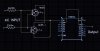
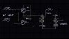
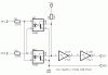
I have two built circuits and I am trying to integrate them. In one ciruit there is 74HC14 IC and there is a 2.2k resister between two gates (pin2 and pin 3) and in other circuit they are directly connected (pin1 and 2). I want to know why is 2.2k resister used? I know the purpose is to invert the output of first gate but why we can't directly connect those pins in both cases?
 
Posting the circuits would help.

Normally an HCMOS intput is directly connected to an output.

Pins 1 and 2 are input and output on the same gate so they shouldn't be connected.

Schmitt gates like the 74HC14 are often used in RC oscillators so the resistor could have been for that.
 
Sorry for the mistake. I wanted to say pin2 and pin3. The two circuits are x10 transmitter and a x10 receiver. 74HC14 is used to detect the zero crossings of the AC power lines. (x10 is a protocol that is used to communicate over power lines) And I want to combine both transmitter and the receiver together and create a transceicver. In the transmitter ciruit pin2 and pin3 of 74HC14 is directly connected and in the receiver circuit they are connected through a 2.2k resister. I want know the difference inbetween so that I can use either directly connection or the connection through 2.2k resister for my combined transceicver circuit.
 

Attachments

  • transmitter.jpg
    transmitter.jpg
    140 KB · Views: 530
  • receiver.jpg
    receiver.jpg
    157.1 KB · Views: 278
I see one way how the 2.2K resistor could make sense.

Something like that:

With the collectors of the optocouplers connected to VCC and the emitters to ground you'd short the supply source when the optocoupler transistors conduct.

Boncuk
 

Attachments

  • HC14.gif
    HC14.gif
    11.3 KB · Views: 1,459
Last edited:
Status
Not open for further replies.

Latest threads

New Articles From Microcontroller Tips

Back
Top