Continue to Site

Welcome to our site!

Electro Tech is an online community (with over 170,000 members) who enjoy talking about and building electronic circuits, projects and gadgets. To participate you need to register. Registration is free. Click here to register now.

  • Welcome to our site! Electro Tech is an online community (with over 170,000 members) who enjoy talking about and building electronic circuits, projects and gadgets. To participate you need to register. Registration is free. Click here to register now.

74190 up/down decade counter help

Status
Not open for further replies.

chelm

New Member
I've searched the forums and there is a thread with this exact title and a very similar question already posted, however the person only reported they figured it out and did not share his method.

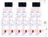
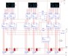
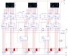
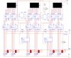
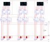
I'm trying to build a countdown clock, I'm at step one which is simply getting one of the circuits to run. I can't get the counter to work at all. I'm using multisim 9 educational, I've attached the diagram of what I have so far. I've pulled the count enable line to high and low with no result.

Any advice is greatly appreciated.
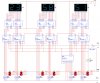
 

Attachments

  • clock3.jpg
    clock3.jpg
    180.5 KB · Views: 5,296
Last edited:
Pin 4 enable needs to be low. The load terminal needs to held high and brought low for an instant.
I think you need to put the 220 ohm resistors to Vcc and let the dip switch pull the appropiate load terminal low.
 
Thanks for the reply!

So is what I have for the most part correct? I'm attaching my latest revision.

A couple questions:

(pin 11) How would I go about setting the load to low and then holding it high? I'm not sure how to do that.

(pin 12 MIN/MAX) Should I do anything with this? I'm not quite sure what it is for.
 

Attachments

  • clock4.jpg
    clock4.jpg
    198.9 KB · Views: 16,171
Last edited:
So this circuit now works from:

99:99:99

But I can't get it to work for:
23:59:59

Again any help anyone can offer is greatly appreciated.

I modified it further an can now get it to set a time to count down. I need to figure out a way to have the div counts start back from what they are set. Currently it counts 5,4,3,2,1,0,9,8,7,6,5,4,3,2,1,0,9... (where it starts at five)
 

Attachments

  • clock6.jpg
    clock6.jpg
    185.7 KB · Views: 5,001
Last edited:
When counters are cascaded like this one of the outputs can be used to load the counters. I am not sure how to do it, perhaps another forum member can be of help. You do need some despiking capacitors of 100nF on a working circuit.
 
chelm said:
So this circuit now works from:

99:99:99

But I can't get it to work for:
23:59:59
You are using all digits to divide by 10 when some should be dividing by 6. Think about it.
 
I've got it so it sets the time now, so I can set it to whatever I want. But you've hit the nail on the head, everything I've tried to do to do a div6, div5, and div3 just mess up the circuit. I tried putting in a D Flip flop, and I've tried logic gates but I can't get any of it to work. If anyone can help lead me down the right path I'd greatly appreciate it.

I think that for the first div6 I need the logic to do the following:
The 74LS190 U4 chip -- when MIN/MAX (pin 12) goes high it means that it has reached zero, so I need to pull the LOAD (pin 11) to Low without pulling the whole line that is connected to the J7 switch. The J7 switch is being used to set the number of hours, minutes and seconds. When it pulls the line to ground the numbers from the bottom row of switches are loaded. Then when I put it back to high the circuit counts down. (with the exception of the div by # not working.

I just want to figure out what I'm doing wrong...

I've tried the following with a D flip-flop, but it messes the circuit up. It doesn't count correctly and I have to completely disconnect the set line (Switch J7).
 

Attachments

  • DflipFlop.gif
    DflipFlop.gif
    4 KB · Views: 1,191
Last edited:
I think I may have used the wrong chips for this. I'm not quite sure how to do a div6 while still being able to preset the numbers. I'm beginning to think it is impossible.
 
Doing the Impossible

Not impossible, just difficult. Difficult we do right away. Impossible just takes a little longer.

You could use a Quad 2-Input Mux such as the 74LS157 to set the counter values for the divide by 6 counters. The Mux SELECT input is controlled by the J7 Preset/Load switch. This allows selection of either the load switch values or the divide by 6 values for the Counter Preset. (The Mux is not needed for the counters that go to 0 and rollover to 9.)

The Mux Select input goes to J7. The Mux I0 DATA inputs go to the Counter Preset Switches and the Mux I1 data inputs go to the desired count preset value for a divide by 6. The Mux outputs go to the counter DATA inputs. In the J7 load position (Mux Select Low), the counter presets are thus connected to the switches. In the J7 run position (Select High) the presets are set to the hardwired values to cause the proper divide ratio. For example the 10's minute digit would be loaded to binary 5 on the next count after it reaches zero.

Since the counter load control is asynchronous you will need a D flip-flop to delay the counter load signal until the count following 00 for the counters you want to divide by 6. Otherwise it would instantly load 5 when it reached 00. Connect the RCO signal from the counter to the D FF input and the FF Q output to the counter LOAD input. The FF clock should be 2Hz for proper sync of the LOAD signal.

You will also need to add 2-input AND gates at the divide by 6 counter LOAD inputs. The AND inputs are the FF output and J7 so either can control the LOAD function for the divide by 6 counters.

Hope you can follow all that. I could draw if for you but what's the fun in that. As they say in the textbooks, that's left as an exercise for the reader. It's not a trivial addition to the circuit but, I think, doable.
 
crutschow said:
Not impossible, just difficult. Difficult we do right away. Impossible just takes a little longer.

You could use a Quad 2-Input Mux such as the 74LS157 to set the counter values for the divide by 6 counters. The Mux SELECT input is controlled by the J7 Preset/Load switch. This allows selection of either the load switch values or the divide by 6 values for the Counter Preset. (The Mux is not needed for the counters that go to 0 and rollover to 9.)

The Mux Select input goes to J7. The Mux I0 DATA inputs go to the Counter Preset Switches and the Mux I1 data inputs go to the desired count preset value for a divide by 6. The Mux outputs go to the counter DATA inputs. In the J7 load position (Mux Select Low), the counter presets are thus connected to the switches. In the J7 run position (Select High) the presets are set to the hardwired values to cause the proper divide ratio. For example the 10's minute digit would be loaded to binary 5 on the next count after it reaches zero.

Since the counter load control is asynchronous you will need a D flip-flop to delay the counter load signal until the count following 00 for the counters you want to divide by 6. Otherwise it would instantly load 5 when it reached 00. Connect the RCO signal from the counter to the D FF input and the FF Q output to the counter LOAD input. The FF clock should be 2Hz for proper sync of the LOAD signal.

You will also need to add 2-input AND gates at the divide by 6 counter LOAD inputs. The AND inputs are the FF output and J7 so either can control the LOAD function for the divide by 6 counters.

Hope you can follow all that. I could draw if for you but what's the fun in that. As they say in the textbooks, that's left as an exercise for the reader. It's not a trivial addition to the circuit but, I think, doable.

I tried following this, but I get lost when trying to connect all the inputs. I hate to ask but is there any way someone can illustrate this? I've changed the clock to what I believe is synchronous, so now what do I do instead of the D FF?
 

Attachments

  • clock15.jpg
    clock15.jpg
    188.6 KB · Views: 3,428
Last edited:
I thought I had this figured out, but now it counts like this: 15-14-13-12-11-10-9-58-57-56...

I have no idea why.
 

Attachments

  • clock16.jpg
    clock16.jpg
    195.4 KB · Views: 1,489
I modified this back to the origional circuit you looked at, I've tried everything I can think off with the clock input of the D FF, I put in a second clock at 2Hz, I've connected it to everything I can think of and it doesn't count quite correctly. It will either not count down the tens of seconds or it will miss a time, it counts the 5 twice when it flips. 00-59-58-57-56-54-53-52-51-50-59-58-57-56-54-53-52-51-50-49-48...

crutschow said:
Not impossible, just difficult. Difficult we do right away. Impossible just takes a little longer.

You could use a Quad 2-Input Mux such as the 74LS157 to set the counter values for the divide by 6 counters. The Mux SELECT input is controlled by the J7 Preset/Load switch. This allows selection of either the load switch values or the divide by 6 values for the Counter Preset. (The Mux is not needed for the counters that go to 0 and rollover to 9.)

The Mux Select input goes to J7. The Mux I0 DATA inputs go to the Counter Preset Switches and the Mux I1 data inputs go to the desired count preset value for a divide by 6. The Mux outputs go to the counter DATA inputs. In the J7 load position (Mux Select Low), the counter presets are thus connected to the switches. In the J7 run position (Select High) the presets are set to the hardwired values to cause the proper divide ratio. For example the 10's minute digit would be loaded to binary 5 on the next count after it reaches zero.

Since the counter load control is asynchronous you will need a D flip-flop to delay the counter load signal until the count following 00 for the counters you want to divide by 6. Otherwise it would instantly load 5 when it reached 00. Connect the RCO signal from the counter to the D FF input and the FF Q output to the counter LOAD input. The FF clock should be 2Hz for proper sync of the LOAD signal.

You will also need to add 2-input AND gates at the divide by 6 counter LOAD inputs. The AND inputs are the FF output and J7 so either can control the LOAD function for the divide by 6 counters.

Hope you can follow all that. I could draw if for you but what's the fun in that. As they say in the textbooks, that's left as an exercise for the reader. It's not a trivial addition to the circuit but, I think, doable.

I've attached what I've managed to get done, but again I'm not quite sure what to do with the clock input line. There is one other issue here as well, when you pull J7 high, it overides the time you input into the switches, just wipes it right out and pushes the time to a 5.
 

Attachments

  • clock17.jpg
    clock17.jpg
    204.5 KB · Views: 979
Last edited:
chelm said:
I've attached what I've managed to get done, but again I'm not quite sure what to do with the clock input line.
The 2 Hz clock should go to the FF CLK, but that's assuming the main clock is 1Hz. You're showing a 200kHz clock. Is that just for test purposes? The FF clock should be twice the input count clock so for a 200kHz input clock, the FF clock should be 400kHz. Also the two clock edges must be simultaneous i.e. the 1Hz clock goes high with the 2Hz clock edge.
 
I have the clock ramped up for testing.

I thought that doubling the clock may be what you meant, so I tried it with 400kHz and it doesn't work.

I'll attach a diagram of the circuit, basically it counts 5 for the tens of seconds twice and does some really strange stuff with carrying through to the minutes place. It's kind of hard to explain. I'll attach my mulitisim file for anyone who may want to have a go at this. I'm about to throw my hands in the air, I've spent an awful lot of time on this and it's just for my own purposes. I recently got my hands on a copy of multisim so I thought I'd see what I could remember from college physics, which is apparently very little.
 

Attachments

  • clock21.jpg
    clock21.jpg
    197.4 KB · Views: 2,269
  • countDownClock.zip
    313.2 KB · Views: 671
I don't have multisim but I simulated the divide-by-five counter on Electronic Workbench. I found a couple problems on my simulation and I don't know whether they apply to your problems but you might check:

1. The standard clock generator model generated two clocks out of phase, i.e. the rising edge of the 1000Hz clock appeared on the following edge of the 500Hz clock. The two rising edges need to be coincident. I corrected that by generating the 500Hz clock from the 1000Hz using the 7474 FF connected as a divide-by-2 (connect D to Q').

2. My 74LS190 simulation model gave an incorrect RCO output. It should be only the width of the negative clock pulse, but it was equal to a whole clock pulse. I corrected that with an added OR gate. (This should only be needed if the simulation model is incorrect. The actual circuit should operate as stated.)

I corrected these errors and it appears to work properly, counting 5, 3, 2, 1, 0, 5, 4,... Attached is a view of the logic simulation.

TRACES
Top - 1000Hz Clock
2nd - 500Hz Clock
3rd - Counter QA Out
4th - Counter QB Out
5th - Counter QC Out
6th - Counter QD Out (Always 0)
7th - RCO Out
8th - D FF Out

Hope this Helps
Counter Out.JPG
 
So are you saying to use 2 FF, one to cut the time in half and the other to control the div counting?
 
chelm said:
So are you saying to use 2 FF, one to cut the time in half and the other to control the div counting?
Yes. I did that because the clocks provided by my simulator were not the phase I needed.

P.S. I noticed in my schematic that the 7474 was not grounded. Pin 7 should go to ground.
 
So I should use the output of the FF that cuts the clock in half to go into the CLK input of the second FF for div counting right? Could I use the output of the FF that cuts the time in half on all of the DIV counters? Or should I have a different one for each div counter? So I know I have to cut the time in half for the tens of seconds, but do I need to cut it in half again for the tens of minutes?
 
Status
Not open for further replies.

Latest threads

New Articles From Microcontroller Tips

Back
Top