Electro Tech is an online community (with over 170,000 members) who enjoy talking about and building electronic circuits, projects and gadgets. To participate you need to register. Registration is free. Click here to register now.
Welcome to our site! Electro Tech is an online community (with over 170,000 members) who enjoy talking about and building electronic circuits, projects and gadgets. To participate you need to register. Registration is free. Click here to register now.
Hi i'm trying to build a 23:59:59:9 coundown i'm using the 74190 up/down decade counter i alredy made it start countdown from 9 to 0 i havent figured out tho how to make it countdown from 5 yo 0 or 3 to 0 or 2 to 0.. can any1 help plz
Hi i'm trying to build a 23:59:59:9 coundown i'm using the 74190 up/down decade counter i alredy made it start countdown from 9 to 0 i havent figured out tho how to make it countdown from 5 yo 0 or 3 to 0 or 2 to 0.. can any1 help plz
You'll need to use the load pin (pin #11) to load a 5 (or what ever number you want to start at), into the counter then have it count down.
you would use the inputs A,B,C,D, (pins 15,1,10,9) to load it in. for a 5, you would want pins a and c to be high and pins B and D to be low (0101)
once those are connected, you would just set the load pin to low for a clock cycle.
when it reaches 0, the MAX/MIN output will go high, use that to detect when it reaches zero, then have that control the load pin. you may need an inverter on it, if the load is active low. (I think my wording is correct, it's been awhile since my intro to digital design class)
I wired the min/max pin to the load pin via a not gate (inverser) it's working fine but it's not displaying the 0.. it's like 5,4,3,2,1,5,5,4,3,2,1...
timewise it's working perfectly but i need to display the 0
hmmm....whats the clock speed? maybe use an AND gate on the MAX/MIN and the RCO (need to invert that as well) If I'm reading the timing chart correctly, it should display zero for 1/2 of a clock pulse.
or you could use the AND on the Min/max and the clock high signal?
I wired the min/max pin to the load pin via a not gate (inverser) it's working fine but it's not displaying the 0.. it's like 5,4,3,2,1,5,5,4,3,2,1...
timewise it's working perfectly but i need to display the 0
According to the datasheet, it should count 5,4,3,2,1,5,4,3,2,1,... without the two 5's in succession as you showed.
I think you can get what you want by connecting MIN OUT to the D input of a 7474, system clock to the CLK input of the 7474, and the Q* (Q-not) output of the 7474 to the LOAD input of the 74190.
ok now it's working perfectly thanks to that 7474 but still i am getting the 5 twise.. i have the clock set on 1 hz every number takes 1 sec to change exept the 5 it's taking 2 seconds as in i'm getting the 5 twise.. how can i salve that??
ok now it's working perfectly thanks to that 7474 but still i am getting the 5 twise.. i have the clock set on 1 hz every number takes 1 sec to change exept the 5 it's taking 2 seconds as in i'm getting the 5 twise.. how can i salve that??
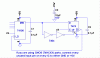
Oops! That's to be expected - add a couple of inverters and a connection to the CLR* pin of the 7474, as below. This will shorten the load pulse so that it ends before the next clock pulse.
Digital logic circuits draw high current spikes from the power supply when the outputs change logic states. That current through the impedance (resistance and inductance) of the power distribution network can cause large voltage transients to appear on the power pins of the ICs, which in turn can cause them to malfunction. The capacitors form low impedance paths for those current transients, resulting in a much "quieter" power supply voltage. See below. You should really have one 0.1uF capacitor across the power pins of each IC package, in addition to one large (10 - 100uF) cap from VCC to GND at some point on the board, preferably at the source of VCC. (VCC in the case below is +5V.)
it's still not working
Look is there any pther way to do it? as in counting down from 5 to 0? as in using another up/down counter chip?? and if there is can u give me it's wiring scheme
it's still not working
Look is there any pther way to do it? as in counting down from 5 to 0? as in using another up/down counter chip?? and if there is can u give me it's wiring scheme
it's still not working
Look is there any pther way to do it? as in counting down from 5 to 0? as in using another up/down counter chip?? and if there is can u give me it's wiring scheme
Instead of trying to shoehorn a 74190 counter into the job why not use the 74LS168 (BCD) or 74LS169 (binary) counters. Their parallel load is syncronous so only occurs on a clock. That way all you have to do is setup the inputs to be 5 (0101) and tie the active low RCO output to the active low LOAD input. Then when the counter reaches 0 it will have 0000 binary on its outputs and the RCO will be low. On the next rising edge of the clock the counter will load instead of count as the LOAD pin has been held down.
This site uses cookies to help personalise content, tailor your experience and to keep you logged in if you register.
By continuing to use this site, you are consenting to our use of cookies.