Continue to Site

Welcome to our site!

Electro Tech is an online community (with over 170,000 members) who enjoy talking about and building electronic circuits, projects and gadgets. To participate you need to register. Registration is free. Click here to register now.

  • Welcome to our site! Electro Tech is an online community (with over 170,000 members) who enjoy talking about and building electronic circuits, projects and gadgets. To participate you need to register. Registration is free. Click here to register now.

74150 Multiplexer help

Status
Not open for further replies.

Zephyr

New Member
Hey,

I've got an ROV project going on in my school, and I want to use a multiplexer to control the motors via MOSFETS or the like.

I'm relatively new to electronics, so, i'll just float a few questions on this board.

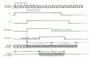
The datasheet's located here

  1. What on earth does a strobe input configure?
  2. When it says Supply current (Max), does it mean I have to add some sort of electronic ballast to limit the current (A small resistor in series)?
  3. What are the data select pins for (ABC)?

I'm using the 151 - but the difference isn't huge. I haven't got much experience in reading data sheets, as you probably can tell.

Any help would be great.
 
Last edited:
hi,
The strobe must be low for the IC outputs to enabled.
Supply current max is the typical current consumption of the iC when its operating... no limiting resistors are required
The 3 pins A,B,C are the address lines used to select the desired input pin.
 
Last edited:
Thanks!

I got everything but the last one. What do you mean by selecting the desired data input pin? Because from what I understand, multiplexers combine those 16 inputs into one output, and i'll need a demux at the ROV side to turn the signal back to 16 outputs.


From what I see of that Demux, I need to have four wires connected - ABCD From the "Data select at the multiplexer", W OUT to either G1 or G2, and holding the other G at low. Is that correct? So I was wrong at my assumption that it's a 16:1 multiplexer, but it actually is a 16:5 multiplexer?

I'm sorry for the jumbled english up there - I hope you understand.

hi,
For the 74LS151 IC.

As an example, say I want to connect the data INPUT pin4 D0, to the OUTPUT pin 6, W.
I would set the address pins ABC 'low',, this is address '0'.
To ENABLE the 'W' output so that it follows the highs/lows on pin4, I also need to set the STROBE [Enable] pin7 Low.

So now whatever state pin 4 is hi/lo, the output pin 7, W will be the same.

If I now want to use pin12 D7 as the INPUT I would set ABC all high, thats address '7'

If I want to block the output from following the state of the input pin I could set the STROBE pin high.

Regarding a DEMUX IC, you would have to use the SAME address states of the MUX IC if you wanted to keep the two IC's in sync.

The DEMUX link you have posted is for a 4 to 16 , which is a different device and not suitable, you need a 1 to 16 [or 1 to 8 for a 151 drive]

I use the HEF4515B
 
Last edited:
Thanks for the Demultiplexer link.

That's precisely what i'm confused with:
data INPUT pin4 D0, to the OUTPUT pin 6, W.
Why would I need to do this? Shouldn't a multiplexer take data from all 16 input pins, combine them into a single output pin, then I'll need a demultiplexer at the other end to turn that single input into 16 outputs?


I'll need to connect the Output Pin W to the HEF4515's Input pin 23 when using it as a demultiplexer.

From what I understand, If I set Pin 8 E0 (151) to high, the corresponding pin 11 Output 0 on the HEF will go high. Is that correct?

Then what are the address lines for?
 
Thanks for the Demultiplexer link.

That's precisely what i'm confused with:

Why would I need to do this? Shouldn't a multiplexer take data from all 16 input pins, combine them into a single output pin, then I'll need a demultiplexer at the other end to turn that single input into 16 outputs?


I'll need to connect the Output Pin W to the HEF4515's Input pin 23 when using it as a demultiplexer.

From what I understand, If I set Pin 8 E0 (151) to high, the corresponding pin 11 Output 0 on the HEF will go high. Is that correct?

Then what are the address lines for?

I think I see your confusion. The mux chip you mentioned selects 1 of 16 inputs based on an address, so only 1 of 16 inputs is available at the output at any one given time. I think what you are thinking of is more of a Time multiplexed bus. See attached timing diagram of a TDM bus

Sorry Eric, not trying to poop in your thread...
.
 

Attachments

  • tdmbus.gif
    tdmbus.gif
    11.8 KB · Views: 1,609
Last edited:
Thanks for the Demultiplexer link.

That's precisely what i'm confused with:

Why would I need to do this? Shouldn't a multiplexer take data from all 16 input pins, combine them into a single output pin, then I'll need a demultiplexer at the other end to turn that single input into 16 outputs?


I'll need to connect the Output Pin W to the HEF4515's Input pin 23 when using it as a demultiplexer.

From what I understand, If I set Pin 8 E0 (151) to high, the corresponding pin 11 Output 0 on the HEF will go high. Is that correct?

Then what are the address lines for?

hi,
I know its an ROV project, but what exactly are the 16 signals sources you expecting to combine into one output.??
 
Hm. For now, how about just either HIGH, or LOW.

I wouldn't expect full data streams as the tether's a bit too long for that.

Many thanks for all the help.
 
Hm. For now, how about just either HIGH, or LOW.

I wouldn't expect full data streams as the tether's a bit too long for that.

Many thanks for all the help.

hi,
Thats not really an helpful answer.:)
If you tell us what you are trying to do I am sure we can help..
 
I'm sorry :p

Well, I have 8 12 DC motors onboard that need to be controlled independently. The tether's 20 meters long, and consists of a power cable and various other data streams (A/V).

Currently, the ROV tether's extremely thick due to a power cable for each of the motors. What I am trying to do is to do something like a H-Bridge for each motor, and one common power cable with 20 phone wire types to control on/off - hence a simple HIGH or LOW would be fine.

And i'm thinking using a PWM to control motor speed - so a data stream would be nice.

But first things first.
 
Last edited:
I'm sorry :p

Well, I have 8 12 DC motors onboard that need to be controlled independently. The tether's 20 meters long, and consists of a power cable and various other data streams (A/V).

Currently, the ROV tether's extremely thick due to a power cable for each of the motors. What I am trying to do is to do something like a H-Bridge for each motor, and one common power cable with 20 phone wire types to control on/off - hence a simple HIGH or LOW would be fine.

And i'm thinking using a PWM to control motor speed - so a data stream would be nice.

But first things first.

Interesting problem.
The surface controller could be a PIC which creates a unique address for each motor followed by the 'command' part of the stream/string,, at the ROV end of the 'serial' cable, a PIC would decode the motor address and send the control command to the addressed motor.
I would also consider the ROV having a return 'line' thru which it can reply/acknowledge the commands.
 
Last edited:
That sounds extremely good - I have actually thought of that, and the added bonus that some PICs have an inbuilt PWM generator, but I have no idea how to program a PIC, and, well - programmers are hard to come by where I live.

Many thanks though.

For educational purposes only - Would a multiplexer work?
 
That sounds extremely good - I have actually thought of that, and the added bonus that some PICs have an inbuilt PWM generator, but I have no idea how to program a PIC, and, well - programmers are hard to come by where I live.

Many thanks though.
For educational purposes only - Would a multiplexer work?

Hi,
For the mux/demux work 'easily', you would have to use 4 wires for the address lines and 1 for the data line.
As the ROV cable is 20 mtrs long I would use a MAX232 line driver/receiver at both ends of the cable, TTL or HEF will not drive a 20 mtr long cable at high data rates.

If you do decide on a PIC system look at the SPI and I2C protocols for ideas.
 
Thanks. Any tips on how to get started with PIC programming?

hi,
A good starting point is the link to Nigels' tutorials near my post signature.
As you may know some PIC's have PWM capability, as well as RS232, which may also be suitable for data transmission for the motors.
 
That link is a marvel.

I'm trying to find a programmer kit online, but i'm having trouble finding the one recommended on that website.

**broken link removed** says on its datasheet that it is compatible with WinPicProg - so i'll give it a try. Many thanks for your help.

Unless you know of some other company with PIC programmers that work with WinPicProg and will ship to China? **broken link removed**
 
Last edited:
That link is a marvel.

I'm trying to find a programmer kit online, but i'm having trouble finding the one recommended on that website.

**broken link removed** says on its datasheet that it is compatible with WinPicProg - so i'll give it a try. Many thanks for your help.

Unless you know of some other company with PIC programmers that work with WinPicProg and will ship to China? **broken link removed**
hi,
I think Nigel is the best guy to ask for that information.
Do you want a PC parallel or serial connection.?
 
I just realised that my computer does not have a parallel circuit, so the link I posted up there would be of no use. Serial it is.
 
I just realised that my computer does not have a parallel circuit, so the link I posted up there would be of no use. Serial it is.
hi,
Look at Bill's link near my post signature, go to his web pages for prommer idea's
 
Last edited:
So would something like the Firefly work with the WinPicProg? The main thing about that program is because they have those great tutorials.
 
Status
Not open for further replies.

Latest threads

Back
Top