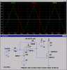
I have a triangle wave input (10 Vpp) and a reference voltage of 5 V. The output square wave should look something like this:
**broken link removed**
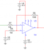
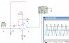
I haven't found any simple instructions on how to go about making this but it should be a simple thing. My simulation is in the attached picture.
So the output is not aligned properly with the input... I tried to mess around with the resistors but it didn't do much.
Any hints would be greatly appreciated.
E: The frequence is 1 kHz.
**broken link removed**
I haven't found any simple instructions on how to go about making this but it should be a simple thing. My simulation is in the attached picture.
So the output is not aligned properly with the input... I tried to mess around with the resistors but it didn't do much.
Any hints would be greatly appreciated.
E: The frequence is 1 kHz.
Attachments
Last edited: