wavestorm1986
New Member
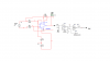
good day to all, i have an ECG project and i must show the heart beat using 7-SEGMENT, means that have to use the PIC16F, so the PIC will work as a ADC to measure the number of heart beat... so i need help to make sure that the seven segment will work as a real time counter for the ECG ....
as far as i know i have to do some calculation to measure the PEAK value for the ECG sequence specially QRS waveform. so any guide for my case ??
thanx in advance
as far as i know i have to do some calculation to measure the PEAK value for the ECG sequence specially QRS waveform. so any guide for my case ??
thanx in advance