Continue to Site

Welcome to our site!

Electro Tech is an online community (with over 170,000 members) who enjoy talking about and building electronic circuits, projects and gadgets. To participate you need to register. Registration is free. Click here to register now.

  • Welcome to our site! Electro Tech is an online community (with over 170,000 members) who enjoy talking about and building electronic circuits, projects and gadgets. To participate you need to register. Registration is free. Click here to register now.

7 Segment LED Difficulties

Status
Not open for further replies.

FLCARM1964

New Member
Greetings all,
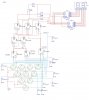
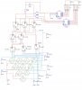
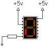
I am still working on a project for my Digital class. I think I am almost done...thanks to Len. However I am having difficulty getting my 7 segment LEDs to work. I am not sure what I have hooked up wrong. I am posting a pic...I am sure some of you will spot my errors immediately. Thank you all for any responses or advice you may have.

Carmine
 

Attachments

  • bowlingpincounter.jpg
    bowlingpincounter.jpg
    147.3 KB · Views: 496
Are they not working at all? Or are they displaying weird patterns? I don't notice a power connection going to the 7-segment displays at all. If you mean the simulation isn't working, you don't have the negative terminal of your 5 volt supply grounded. One thing that is missing is resistors. You need a resistor between each line going from the 7447 to the 7-seg. Also another thing to check is whether you have common anode or common cathode 7-segments. You may need to add inverters to each output of the 7447. Also, make sure that the /LT inputs are tied high, you leave them floating. Just my initial observations.
 
Sir,
No they are not working at all. I placed grounds where needed. I am now using common anode displays Anything else come to mind?
Carmine
 

Attachments

  • bowling_pin_counter_rev1.jpg
    bowling_pin_counter_rev1.jpg
    149.1 KB · Views: 519
Take a 7-segment display out of the circuit and place it somewhere else on the breadboard so other wires aren't interfering with it. Connect your common anodes to the +V bus (could be two of them, check datasheet). Then take a resistor, say around 220 to 470 ohms, and place it between one of the segment inputs and ground. One of the segments should light up. If that doesn't work, try the other segment. If that doesn't work, steal one from lab. Maybe you got two unlucky ones that are bad.

Like I said in my previous reply, you are going to need a resistor between every connection from the 7447 to your 7 segment display.
 

Attachments

  • 7seg.png
    7seg.png
    1.3 KB · Views: 420
Problem solved!

Bonxer,
Yesterday when you made some suggestions; one being to tie my pins to a high ( Pins 3,4 & 5) on U11/U13. It worked!!! I did not add the resistors, I guess Multi Sim is designed to do that. Anyhow, I wanted to say thank you for your advice over the last couple of weeks. Perhaps someday I will be able to provide guidance to others as well.

Carmine
 
Multi Sim doesn't know that the LEDs in the display will melt without current-limiting resistors.
 
Status
Not open for further replies.

New Articles From Microcontroller Tips

Back
Top