Electro Tech is an online community (with over 170,000 members) who enjoy talking about and building electronic circuits, projects and gadgets. To participate you need to register. Registration is free. Click here to register now.
Welcome to our site! Electro Tech is an online community (with over 170,000 members) who enjoy talking about and building electronic circuits, projects and gadgets. To participate you need to register. Registration is free. Click here to register now.
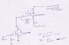
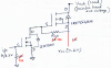
As per your suggestion. I have attached the schematic. Correct me if I am wrong with its understanding.
Giving 3.3V (Logic high from the microcontroller) will turn on 2N7000 and because its source is connected to ground, the same is given to gate of IRF9540 and this will turn on IRF9540 and we get 7.2V at the output.
When 0V (Logic 0) is given, 2N7000 is OFF and Rgs will take care of pulling the gate of IRF9540N to Vcc (ie 7.2V) thereby keeping it in OFF and the output is open.
My doubts.
Is 7.2V, 3Amp work with IRF9540 and is 7.2V needed for gate of IRF9540N.
Meanwhile, I am from INDIA. I need to still find out if these parts will be available here.
You are using an RGS of only 1k for both mosfets which is too low. The micro-controller cannot drive a load as low as only 1k without dropping its voltage to maybe only 3.0V when high and the 2N7000 cannot drive a load as low as 1k with only 3.0V on its gate. Use 10k.
You are supplying the source of the P-channel Mosfet through a 1k resistor so its output is only 7.2mA into a short and 7.2V when it has no load. Get rid of this 1k resistor.
I'm glad you spoke up, Audioguru. This appeared to be a classic case of the blind leading the blind. Some people need to know when to just shut up and "listen".
I'm glad you spoke up, Audioguru. This appeared to be a classic case of the blind leading the blind. Some people need to know when to just shut up and "listen".
Blueroomelectronics. Agree to what you said about students. I am hoping more people come forward and help. Whats the use of having knowledge and not willing to share it
By the way. what do u mean when u say blind leading blind... u mean to say that we are going in a wrong direction with this???
well I've used this very setup before, output is triggered by well under 2V and I never spoke of resistor values so if I'm the blind leader the one that don't even read posts properly better get his eyes checked first ! The unnecessary arrogance on this board is the reason I scarcely bother visiting anymore
well I've used this very setup before, output is triggered by well under 2V and I never spoke of resistor values so if I'm the blind leader the one that don't even read posts properly better get his eyes checked first ! The unnecessary arrogance on this board is the reason I scarcely bother visiting anymore
Thunderchild, I wasn't referring to you.
I had a brain fart. I had looked at the schematics that were posted, and failed to notice that they had been posted by the OP, in an attempt to understand and reproduce what people had been telling him. I thought that the schematics had been posted by some bozo who was giving the OP bogus advice.
In short, I violated my own advice: Always read the entire thread before commenting.
This site uses cookies to help personalise content, tailor your experience and to keep you logged in if you register.
By continuing to use this site, you are consenting to our use of cookies.
")