Continue to Site

Welcome to our site!

Electro Tech is an online community (with over 170,000 members) who enjoy talking about and building electronic circuits, projects and gadgets. To participate you need to register. Registration is free. Click here to register now.

  • Welcome to our site! Electro Tech is an online community (with over 170,000 members) who enjoy talking about and building electronic circuits, projects and gadgets. To participate you need to register. Registration is free. Click here to register now.

5x7 LED Board 2 Wire

Status
Not open for further replies.

AtomSoft

Well-Known Member
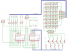
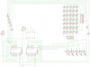
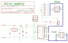
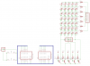
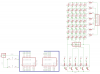
Hey people i just wanted to share my laest project. Its a 5x7 LED board with only 2 PINS Needed.I wired it up like the 2 wire LCD project thats been going around. The only difference is that instead of 1 SN74ALS174 i used 2 wired to each other so when it shifts it will shift 12 bits instead of 6 bits. Since it is a 5x7 = 5 Columns + 7 Rows to control = 12 bits in total so i guess it worked out 100%. I have posted my code and a picture of it below. I will make a schematic ASAP to post here. I hope this can inspire/help someone out there. At least as a example.

**broken link removed**
 

Attachments

  • led_bc_5x7.zip
    22.9 KB · Views: 145
Here ya go... it might look confusing but thats the best i can do at 12:50am

**broken link removed**

D/C is Data & Clock i used RB1 & RB4.
 

Attachments

  • 2wireleda.png
    2wireleda.png
    58.3 KB · Views: 162
Last edited:
Nice work.But I would simply use a whole port from micro (8 or 7 pins to drive rows).& to drive serial register (column side) I use 2 or 3 pins (74HC164) from micro.This way it looks a good wiring & a nice looking code.
 
The main reason is so you can have more pins on the uC left over. Like if your using a 8-16 pin uC you still have some left. Wont eat a whole port. I dont have a 74HC164. This works well tho.
 
Hey i altered the code so you can easily pick a row and set the column. Also added a sample countdown.
Since it take 14 ms to display 1 digit and lets say you want to show it for 2 seconds. You would:
1000ms(1s) / 14 = 71.41 which would be the number of times to show it for 1 secone

71.42 * 2 = 142.84 (142-143) So you would show it about 142 times for a 2 second delay.

Enjoy!
 

Attachments

  • main.c
    2 KB · Views: 157
  • config.h
    423 bytes · Views: 137
New code again lol finished numbers with full 9-0 countdown

Better delay and look n feel.
 

Attachments

  • led_bc2.zip
    1.2 KB · Views: 125
Last edited:
Here ya go... it might look confusing but thats the best i can do at 12:50am
D/C is Data & Clock i used RB1 & RB4.
I know it was late and this was a quick job, and it is nice. If you have not used them look in to using buses (tool next to net). Also you do not need to show a continous net for every connection. As long as the names are the same they are connected. See A0 on the activity connector under the motor connector.

The attachment upload problems have been fixed. If you upload attachments here they will be around for as long as the forum. Not too sure about photobucket.
 

Attachments

  • PIC18simple.png
    PIC18simple.png
    105 KB · Views: 184
Last edited:
cool ill try to see if i can make a bus right now but will be difficult since its 1Q to 2D Can i (re)name the pins? Or just leave it as is without the bus?
 
cool ill try to see if i can make a bus right now but will be difficult since its 1Q to 2D Can i (re)name the pins? Or just leave it as is without the bus?
1A and 2D are pin names. You can name the net connecting them with either name or come up with a new one that makes sense. The net name will be the same wherever it pops out of the bus.
 
Here is the new schem. How would i calculate how much current i need to drive these buggers? Should i just calculate like for 1 row of leds since that all that is on at 1 time.
 

Attachments

  • 2wireledc.png
    2wireledc.png
    19.1 KB · Views: 164
New code and with a scroll now. Need to work on scroll more but heh im tired


EDIT : Fixed Scrolling
 

Attachments

  • led_bc3.zip
    1.2 KB · Views: 110
Last edited:
Here is the new schem. How would i calculate how much current i need to drive these buggers? Should i just calculate like for 1 row of leds since that all that is on at 1 time.
That makes sense to me. But then I am a software guy.

On the schematic. I would only use the bus for signals going from the 174's to the display. Use the "ABC" tool to show the name of each net where it enters and leaves the bus. With the nets that stay within the two 174's I would show the nets.
 
Not a problem. There are a few different ways to draw a schematic. Some are mostly a set of chips with the net names marked on each pin. Some make use of buses. Others show evey connection as in your first schematic.

I took a quick look but did not see any change in the new schematic. You are not showing what is going on around the 174's and there is no bus between the 174's and the display.

Have the signals enter the bus at the 174's and exit and connect to the display circuit parts.

If you want to post the original schematic I will make a few quick changes to show you what I am talking about. :) Or not. :)
 
This is a modified version.
You do not need to add the junctions. You only need to see the dot where wire meets wire not where wire meet component pin.
 

Attachments

  • Untitled2.png
    Untitled2.png
    47.6 KB · Views: 155
  • 2wire.zip
    101 KB · Views: 113
Last edited:
Status
Not open for further replies.

New Articles From Microcontroller Tips

Back
Top