Continue to Site

Welcome to our site!

Electro Tech is an online community (with over 170,000 members) who enjoy talking about and building electronic circuits, projects and gadgets. To participate you need to register. Registration is free. Click here to register now.

  • Welcome to our site! Electro Tech is an online community (with over 170,000 members) who enjoy talking about and building electronic circuits, projects and gadgets. To participate you need to register. Registration is free. Click here to register now.

555 Timing delay

Status
Not open for further replies.

jelle2503

New Member
Hi everyone,

I'm in need of some guidance.

I've been looking for approx 2 weeks now online for many many hours, and have been experimenting with breadboard since 3 days to achieve a simple thing. I have read and seen many circuits on many different website. Have read for hours through 555 datasheets to understand it's working. Haven't lost interest.

I have a signal wire, it gives 0,5 seconds of 12V upon pressing a button.

But I need to delay this brief signal for 4~ seconds.

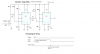
I have added GO.png, it was my first attempt to make this. I have created both circuits, but in both diagrams they depend on the TRIGGER signal to go low, which does not apply to me.

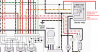
Meanwhile I found DF90.png, it looks very much as to what I need, perfect! On this website.

I know how to calculate time in seconds (t=1.1xRxC), but in DF90.png I can not figure out which ones to calculate for me to adjust the timing. The output pulse in DF90 is too short.

So my question, anyone knows which R to multiply with C, to adjust delay time? AND which R x C, to adjust pulse time output? I use 390K and 1uf for 0,42s pulse, and 820K and 4,7uf for a 3,6s delay.

Or maybe you can help me reverse polarity on my GO.PNG circuits so I can use these circuits for my purpose? I do not want the trigger signal to have to become low. The trigger must be the 0.5 seconds of 12v current.

I've been kind of stuck on this for long now. And am desperate for a solution. Also am looking to buy someone off to make this for me, or to pay someone making me a circuit with either one 555, dual 555s, or a pre programmed microcontroller that fits my needs.

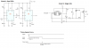
Help is very much appreciated. Naamloos.png is included as how I want the timing diagram to work.

Cheers, from Amsterdam, Netherlands.

Jelle
 

Attachments

  • GO.png
    GO.png
    36.7 KB · Views: 228
  • DF90.png
    DF90.png
    38.8 KB · Views: 246
  • Naamloos.png
    Naamloos.png
    6.1 KB · Views: 206
Last edited:
The circuit you linked to was designed by Mike one of the forum members, hopefully he will come along and modify it to suit your needs.

As to the triggering scheme he uses a transistor to invert the trigger signal thus getting a negative pulse trigger.

Another common circuit to get you where you want to go involves the use of a 556 timer (or a pair of 555 timers) and I have attached an old image of such a circuit. The credit for the attached goes to Forrest M Mimms III and it is from an old 80s engineers notebook. If you look at it it id a pair of 555 timers set up as a one shot monostable configuration where the output of the first triggers a second after a delay.

Ron
 

Attachments

  • Two Stage Timer Small.gif
    Two Stage Timer Small.gif
    683.1 KB · Views: 252
hi,
The dual 555 circuit shown in your post is the one I would use, add the inverting transistor for the Trigger as shown in DF90 image.

The DF90 image shows pin 3 connected to a differentiator R/C transistor circuit, which will give a delayed pulse, but its not as precise as the dual 555 or the 556 that Ron has posted.

if you need a circuit, ask.
 
yes I do need a drawn circuit (I'll Paypal you 10 euro's if it'll fit my purpose).

It's kind of embarrassing as I normally do not need to ask for help on pretty much all info I required so far, but this one is grinding my gears a little too much. I'm trying, and I'm getting there, but I need some help or it's gonna take a year.

If someone could add that inverting transistor in to the scheme with the 555, I'd be delighted! That'd mean I can build on this scheme (which I am able to manage) and hopefully have it work.

As for now, thanks for the suggestions.

I hope it's clear my trigger is a short 0.5 seconds of 12v. I need to pause and replicate this pulse by delaying with dual 555.
 
Last edited:
yes I do need a drawn circuit (I'll Paypal you 10 euro's if it'll fit my purpose).

It's kind of embarrassing as I normally do not need to ask for help on pretty much all info I required so far, but this one is grinding my gears a little too much. I'm trying, and I'm getting there, but I need some help or it's gonna take a year.

If someone could add that inverting transistor in to the scheme with the 555, I'd be delighted! That'd mean I can build on this scheme (which I am able to manage) and hopefully have it work.

As for now, thanks for the suggestions.

I hope it's clear my trigger is a short 0.5 seconds of 12v. I need to pause and replicate this pulse by delaying with dual 555.

hi,
I will post a circuit over the weekend for you.
It will be a pair of 555's or 556 dual, I guess you can get either type locally.

BTW: we give our help free of charge.
 
Last edited:
hi.
Look at this option.
Image also shows LTspice simulation.

RT1 and RT2 can be selected to suit timing periods

You dont say what the output2 is driving into.???
 

Attachments

  • 556Dual1.gif
    556Dual1.gif
    42.6 KB · Views: 229
My remote start signal needs to be delayed. All the alarm does is send a short 12v pulse to the starter relay coils, and a constant to ACC/ON upon pressing the button on my remote. This will start the engine without key by remote. But sadly this alarm does not come with a Time to Delay option on the starting. My ECU needs ~4 seconds time to do some procedures, then I can start it.
Thanks for the free help ;) but seriously I don't mind paying for someone's time and knowhow. I want to show my gratitude :D I'm very appreciative
Kind of bothers me especially since I'm too much of a nub to figure it out myself and have to come and ask as a newbie on a forum -_-
Not much free time too kind of limits me.

So this circuit will output a short high signal once, when triggered with a short high signal once?
The timing bar in your diagram, looks as if it's repeating. Could be wrong. Maybe you misunderstood, I need both 555 in one-shot (I believe that's what it's called.)

edit: nvm, I misread that time graph. It requires a high trigger to active a delayed pulse. It's not repeating. Thanks for the help dude I'll let you know in the next week what happened!
 
Last edited:
Its only shown to be repeating for the sake of the simulation, I input two test pulses.

It will only give one delayed pulse for every input pulse in the way you asked for.!!
 
Yes man. :) I hadn't taken a close enough look. Excuse me

If you don't mind I have reworked your scheme for dual 555. Just because I have them here. And I did it to understand the scheme a bit more. I think it's OK :)

btw what's that program you're working with?
 

Attachments

  • solution.png
    solution.png
    34.8 KB · Views: 216
Last edited:
Yes man. :) I hadn't taken a close enough look. Excuse me

If you don't mind I have reworked your scheme for dual 555. Just because I have them here. And I did it to understand the scheme a bit more. I think it's OK :)

btw what's that program you're working with?

Its LTspice, a free download simulator.
 
I was just about to edit my post, as I already googled information on it just like now, got myself a 2.2mb Starter guide to work on :)

I'll be looking to try this all out :) Again thanks for the help, it's much appreciated.
 
I was just about to edit my post, as I already googled information on it just like now, got myself a 2.2mb Starter guide to work on :)

I'll be looking to try this all out :) Again thanks for the help, it's much appreciated.

I would recommend that you join the Yahoo LTspice User group. lots of examples/samples etc.
 
Woot

Yo eric, thanks for the helping hand.

Here's what I managed to make! Can't believe I finally pulled it off.
Breadboard test:
**broken link removed**

My final first homebrew "modchip" ;) So proud :D
**broken link removed**

Did I pass? Or fail. I find it kind of amusing I just started this electric stuff and it all worked out. Thanks to you ofcourse.
Donno if this build is considered noobie, but I suppose it is. I however think it looks pretty neat for a first, with 0 experience mapping these circuits.

I think this tops having soldered in a Cygnos V2 in a brand new Xbox 360 with just 1 hour soldering experience and having it actually work.

I'll make a vid of my remote start procedure as soon as I have it hooked up.

What would you recommend Eric? To connect VCC to constant source with fuse (battery), or to connect VCC to my ACC/ON on my ignition (switched). I noticed the circuit will sometime output a pulse even if not triggered when I connect the ground and VCC for the first time.

I'll join that group. I can learn more.
 
Last edited:
Yo eric, thanks for the helping hand.

Here's what I managed to make! Can't believe I finally pulled it off.
Breadboard test:


My final first homebrew "modchip" ;) So proud :D


Did I pass? Or fail. I find it kind of amusing I just started this electric stuff and it all worked out. Thanks to you ofcourse.
Donno if this build is considered noobie, but I suppose it is. I however think it looks pretty neat for a first, with 0 experience mapping these circuits.

I think this tops having soldered in a Cygnos V2 in a brand new Xbox 360 with just 1 hour soldering experience and having it actually work.

I'll make a vid of my remote start procedure as soon as I have it hooked up.

What would you recommend Eric? To connect VCC to constant source with fuse (battery), or to connect VCC to my ACC/ON on my ignition (switched). I noticed the circuit will sometime output a pulse even if not triggered when I connect the ground and VCC for the first time.

I'll join that group. I can learn more.

Hi,
Well done.!:)
It is neat and tidy, pleased to see that you built it on a bread board first, always a good idea when learning.
Looking forward to seeing the vids.

The 555 circuits will sometimes trigger when power is applied, its possible to use the RESET on the 555 to prevent this from happening if its a problem.

For the time being until you more confident that the timer works as you expect, I would use Vcc to its own source.
 
So today I figured it'd be a good day to fit my "chip" into my motorcycle.

Before I hooked it up permanently, I had it ghetto rigged to see if it would output. I used a currentseeker with light (rough translation), and it would light up. So I went ahead and hooked it into my wiring to see if it would work. Used the remote on my alarm to start, and expected a 3 second delay before starting... Nothing... Now it doesn't seem to output a 12v pulse anymore. On the output I measure 0,56v. And if I remove ground from the circuit, it will output a 12v constant (that seems to be normal)

I use a Xbox 360 PSU, so I can supply the circuit with 5V and test it. Whenever I do this the timer still works perfect. 3 seconds of delay and then the led comes on for a split second.

I checked ground and VCC with multimeter diode setting and that doesn't seem to be the problem. I think I might've burnt something?
 
Last edited:
hi,
I asked this question in post #6.
You dont say what the output2 is driving into.???
Post a digram how it is connected in the final project.
 
It's thesame place where I hook up my starter wire coming from my alarm. I included a picture.
 

Attachments

  • nm.png
    nm.png
    1.2 MB · Views: 195
Last edited:
It's thesame place where I hook up my starter wire coming from my alarm. I included a picture.

There is no way that 555 output will drive a starter relay, you need a medium power transistor or MOSFET between the 555 pin 3 and the coil.

EDIT:
A quick look at the wiring diagram, you may require steering diodes in the relay connecting wires.
 
Last edited:
So what makes the delayed 555 output pulse different than the alarm output pulse? The alarm output pulse can activate the starter relay just fine.

Could you please be any chance update the diagram for me? :eek:

And is my circuit broken now? Since it won't output anymore on 12v, even though it seems to work perfect with 5v?
 
Last edited:
This is the way I would do it, ref image.

The 1sec pulse has to switch ON a 12Vsource that can supply sufficient current to operate the starter relay. You could use a PMOS FET instead of the relay, but would not be my choice.

The NMOS FET and relay could be mounted on a small pcb between the 555 output and the starter, no changes to your finished pcb.

NOTE: the 12V battery connection
 

Attachments

  • AAesp11.gif
    AAesp11.gif
    24.9 KB · Views: 199
Status
Not open for further replies.

Latest threads

New Articles From Microcontroller Tips

Back
Top