Continue to Site

Welcome to our site!

Electro Tech is an online community (with over 170,000 members) who enjoy talking about and building electronic circuits, projects and gadgets. To participate you need to register. Registration is free. Click here to register now.

  • Welcome to our site! Electro Tech is an online community (with over 170,000 members) who enjoy talking about and building electronic circuits, projects and gadgets. To participate you need to register. Registration is free. Click here to register now.

555 timer frequency change problem

Status
Not open for further replies.

i12know

New Member
Hi guys,

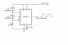
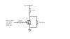
I am using a 555 timer to create a 40kHz output signal. I have manage to generate that easily with a circuit built based on guide I found on internet, connecting with 2 resistor and 2 capacitor. But the problem that I found with that timer is that the output frequency of the circuit is changing with the supplied voltage. The supplied voltage range for the timer is 5V to 15V, and when I supply the voltage outside that range, the output frequency changes dramatically, which should be normal, but when I change the supply voltage between 5V and 15V, the output frequency still changes a bit, which I find is odd (When I supply 5V and tuned it to 40kHz, and increase the voltage slowly until around 15V, the frequency will increase till about 42.5kHz, and in my application, I would like it to be fixed at 40kHz). I thought it should not do that when it is running normally in its voltage range, as in, the output frequency should not be affected by the supplied voltage. I would like to ask, is that normal that the frequency will change even in its supply voltage range? Or it is just some fault with the circuit or my 555 chip? If it is normal situation, could you guys explain a little bit more in detail why is that so?

Thanks a lot guys.
 
I've not directly experience this but noticed that when i did a speed control using variable duty cycle and suposedly a fixed frequency it would vay the frequency a bit with duty cycle, my conclusion is that the 555 is not the most stable oscilator but it is an old favourite and easy to use
 
Post your oscillator circuit. I want to see what you are doing in the timing network.
 
Last edited:
The 555 timer isn't known for its stability and some ceramic capacitors change their capacitance as the voltage applied across them is increased.
 
The frequency also changes with temperature. I've had a circuit I built years ago, install in my carport, and still running 24/7. Sometimes I hear a 'click' from the speakers, on warm days, I can hear a tone. Normally, I don't hear anything from it.
 
I have attached my oscillator circuit in the post here. The output from pin 3 will be used to drive a transducer that has a resonance frequency of 40kHz. I have tuned both my potentiometer to different values, which I can't remember now, but the output signal is 40kHz. Just that it changes with the voltage sometimes.
 

Attachments

  • LM555..JPG
    LM555..JPG
    14.8 KB · Views: 1,019
Last edited:
Seems like the conclusion would be that 555 timer is not really stable and that problem is not a technical problem that can be fixed? Like adding some other electronics parts?
 
I would try using larger timing resistors, and a smaller timing capacitor. I would also make sure that there are 1 ea 0.01uF disc ceramic and a 10uF tantalum or electrolytic bypass capacitors between Vcc and Ground. Try putting a 47 or 100 Ohm resistor between pin 3 and your transducer, too.
 
Last edited:
I have attached a picture of my output circuit as well, and I have a 22ohm resistor between pin 3 and the transistor, not sure is it big enough though, as you have suggested a 47 or 100ohm resistor. And can you explain further what is the reason for adding the different capacitors between the Vcc and ground?

At this stage I do not require a highly stable circuit, therefore might not be doing those changes just yet, but I am curious about how the situation occurs (Vcc affects the frequency) and how does adding those capacitors fix the problem.
 

Attachments

  • output..JPG
    output..JPG
    19.6 KB · Views: 419
The 555 is notorious for having "shoot-through" current in its output stage as the output switches high or low. If there is not an (energy storage) bypass cap across the VCC to GND pins very close to the 555 package, the inductance of the power leads can cause the voltage across the 555 to sag as the output switches. This can (and does) perturb the comparators inside the 555, causing erratic timing.

Your output stage sucks. Yes, the base resistor needs to a few hundred Ohms. The transducer should be moved between the collector and the positive supply. Does your transducer tolerate a drive voltage with a DC component, or should it be driven with an AC signal?
 
Seems like the conclusion would be that 555 timer is not really stable and that problem is not a technical problem that can be fixed? Like adding some other electronics parts?

You need a crystal controlled oscillator.

Digikey sells 40kHz crystals which can be used to make an oscillator by adding a logic gate.
**broken link removed**

**broken link removed**

C1 and C2 should be 12pF, the remaining gates can be used to buffer the oscillator.

You'll need a low dropout regulator such as the LM2936-5.0 to run from 5V to 15V, otherwise you'll need to use the CD4049 and a couple of transistors to drive the piezo.

If you can't find a 40kHz crystal from a convenient supplier, so you'll need to use a higher frequency and a divider, for example 1MHz and a divide by 25 or a 4MHz and a divide by 100 counter.
 
A crystal controlled circuit is perhaps your best bet. BUT if your intent on using a 555 then, as I understand it, a 7555 is a more stable part.
Dead on accuracy go with a crystal. I recall seeing a 555 using a crystal and generating an accurate 60hz for a clock.
 
Your output stage sucks. Yes, the base resistor needs to a few hundred Ohms. The transducer should be moved between the collector and the positive supply. Does your transducer tolerate a drive voltage with a DC component, or should it be driven with an AC signal?

I have tried connecting the transducer to between the collector and the positive supply before and it doesn't work, that is why I change to this setting, and it work for me though. Could it be because of the small resistor that I used that cause the circuit not working when I connect the transducer and the transistor in series? Nope, it has to be driven with an AC signal.


If you can't find a 40kHz crystal from a convenient supplier, so you'll need to use a higher frequency and a divider, for example 1MHz and a divide by 25 or a 4MHz and a divide by 100 counter.


And yup, I will get a crystal one if I need it to be in high precision. But what divider did you mean here? Could it be a frequency divider circuit that is using a 555 timer that I had seen in the web?
 
I have built many oscillators with the 555 timer. I agree with MikeMI about the filter capacitor between pin 8 and ground. Also the 0.01uF capacitor from pin 2 to ground should be a good quality film capacitor. I also always make sure that the resistance from pin 7 to Vcc never gets below 1K as there can be excess current into pin 7.
 
I have built many oscillators with the 555 timer. I agree with MikeMI about the filter capacitor between pin 8 and ground. Also the 0.01uF capacitor from pin 2 to ground should be a good quality film capacitor. I also always make sure that the resistance from pin 7 to Vcc never gets below 1K as there can be excess current into pin 7.

Ooppss... I just checked my resistance there and it turn out to be 226Ohm and 1.428kOhm for another resistor. Before this I am using a fix resistor between pin 7 and Vcc with a value of 1k, but then I get a frequency output with duty cycle of about 70-80%, therefore I changed to a potentiometer there and tune it to get a 50% duty cycle, and the tuned value turn out to be the value that I have got there. Seems bad there, but if I tune it higher than 1k, then I might not get a 50% duty cycle anymore.
 
do you mean like a D flip-flop or something similar as the counter?
Yes the idea was to use a counter to get 40kHz from a higher frequency.

What's your location?

Farnell sell 40kHz crystals as well as Digikey. They are cheap so save yourself the trouble and go with the circuit I posted previously.

Your Search Results | Farnell United Kingdom
 
Yes the idea was to use a counter to get 40kHz from a higher frequency.

What's your location?

lol, i am not in UK now, i am in NZ, but there is a Farnell branch here as well. Will get one of those and try it out.

Thanks a lot guys for all the help. Really grateful for that. And really grateful with all the prompt replies. Thanks again!!
 
I have built many oscillators with the 555 timer. I agree with MikeMI about the filter capacitor between pin 8 and ground. Also the 0.01uF capacitor from pin 2 to ground should be a good quality film capacitor. I also always make sure that the resistance from pin 7 to Vcc never gets below 1K as there can be excess current into pin 7.

Probably I could reduce the value of the capacitor as well to increase my resistance value from pin 7 to Vcc, I guess.
 
Status
Not open for further replies.

Latest threads

New Articles From Microcontroller Tips

Back
Top