Continue to Site

Welcome to our site!

Electro Tech is an online community (with over 170,000 members) who enjoy talking about and building electronic circuits, projects and gadgets. To participate you need to register. Registration is free. Click here to register now.

  • Welcome to our site! Electro Tech is an online community (with over 170,000 members) who enjoy talking about and building electronic circuits, projects and gadgets. To participate you need to register. Registration is free. Click here to register now.

555 timer circuit - why so much voltage drop?

Status
Not open for further replies.

emc2

New Member
Hi,

I'm just beginning to play around with some small circuits and have created a simulation in electronics workbench.

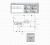
The circuit seems to work but there is a drop in voltage (look at the multimeter).. Why is that? When I actually build the circuit on a breadboard the led (instead of the multimeter) is really dim..

Can anyone explain why there is such a big voltage drop and if i can change the circuit for it to output more volts.
 

Attachments

  • Capture.JPG
    Capture.JPG
    204 KB · Views: 276
Your sim scope reading looks right. You can't measure pulses with a multimeter. Your LED is probably dim because your batt is low and also your LED is off for half the time, maybe your LED series resistor is too big. What value series R are you using for the led?
 
Last edited:
The 'scope shows 9V p-p like a Cmos 555. An ordinary 555 will have an output of only 7.7V p-p when the supply is exactly 9.0V.
With an LED connected from the output to ground without a current-limiting resistor the Cmos 555 will light the LED dimmly if the supply remains at 9.0V.
But an ordinary 555 has an output high current exceeding 200mA so the LED will blow up.

Brilliant! that explains alot and gives me something to work with.. It also explains why 2 LEDs have blown!!

Right back to work :)
 
Connecting a resistor in series with an LED limits its current. The resistor value is simply calculated with Ohm's Law and grade 3 (when you were 8 or 9 years old)arithmatic.
 
A multimeter can read a 50Hz or 60Hz sine-wave accurately.
The very low frequency and square-wave from the 555 will measure terribly wrong.
 
Status
Not open for further replies.

Latest threads

New Articles From Microcontroller Tips

Back
Top