shaneshane1
New Member
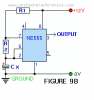
Hi im trying to work out how to get a 1 second square wave from a 555, im not to sure how to obtain this wave.
I want the output to be High for 1 second and then low for 1 second and so on, i have searched google, but cant find anything i can fully understand.
I want the output to be High for 1 second and then low for 1 second and so on, i have searched google, but cant find anything i can fully understand.
")
