Continue to Site

Welcome to our site!

Electro Tech is an online community (with over 170,000 members) who enjoy talking about and building electronic circuits, projects and gadgets. To participate you need to register. Registration is free. Click here to register now.

  • Welcome to our site! Electro Tech is an online community (with over 170,000 members) who enjoy talking about and building electronic circuits, projects and gadgets. To participate you need to register. Registration is free. Click here to register now.

555 Pulse Output project help

Status
Not open for further replies.
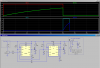
okay 12v power will come on and remain on, i want the constant 12v to cause a pulse thats delayed 10 seconds, goes high for one second and then goes low and stays low. it would need to reset when the constant 12v is removed. id perfer to use a 555 or 556 timer for this if possible, oh and the pulse will be used to control a 12v micro relay.
please include diagrams if possible thanks guys

I believe this circuit will work for me, but i would like to increase the delay to 10 seconds and the initial trigger will remain on so how can i have that not affect the function?

**broken link removed**
 
Last edited:
The circuit you posted requires application of 12V, and subsequently that you push the start button. Is that what you want? Or do you want it to start the timing cycle automatically when the 12V is applied?
 
What is the load that this switches. Are you sure you need a relay?
 
Here is a hack. U1 comes up triggered, and times out after 10sec. The down edge of U1 triggers U2, which times out in 1sec. R4-C4 guarantees that both U1 and U2 come up in the correct state when power is applied by the KeySwitch. R1-C1 makes the first delay. R5-C5 sets the pulse width. The transistor on the output switches its collector to ground during the pulse. If your load is inductive, you should add a snubber diode.
 

Attachments

  • DF54.png
    DF54.png
    38 KB · Views: 233
The ACCY (switched) power connects to the wire labeled "SwVcc", as shown in the schematic. You said that one end of your load is connected to switched 12V (Presumably SwVcc), and the circuit is supposed to ground the other end of your load for the duration of the pulse. That is what R7 represents.
 
Last edited:
Awesome and it won't matter that the input will be 12v all the time?

The whole purpose of the circuit is that it makes one pulse each time the ACCY switch is closed, no matter how long the switch stays closed...
 
Last edited:
Status
Not open for further replies.

New Articles From Microcontroller Tips

Back
Top