Continue to Site

Welcome to our site!

Electro Tech is an online community (with over 170,000 members) who enjoy talking about and building electronic circuits, projects and gadgets. To participate you need to register. Registration is free. Click here to register now.

  • Welcome to our site! Electro Tech is an online community (with over 170,000 members) who enjoy talking about and building electronic circuits, projects and gadgets. To participate you need to register. Registration is free. Click here to register now.

555 Dark Detector Circuit Help

Status
Not open for further replies.
Suraj143 said:
What an expression now only I understood what’s the meaning of threshold voltage. The threshold voltages are the voltages at which the output of the Schmitt changes state. There is an upper threshold Vt+ and a lower threshold Vt-. When the input voltage of a 74HC14 rises to Vt+, the output goes from high to low. There is no change, if the input voltage rises further. However, if the input voltage is reduced, there will be no change until it falls to Vt-, then the output will go from low to high.

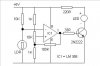
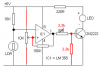
Ijcox don’t scold me (I did not think I was scolding you) for that LM358 circuits output I connected the base of the 2n2222 via 33ohm resister. I assume that this is resistor R4 in the circuit you gave us a link to. Is this correct? Now I have to use a 2N7000 n channel one as you said.
But do I need a base resister for that?
You do not seem to have read what I wrote in red in my previous post.

I said that you could put a red LED in series with the base resistor (R4) which should make the transistor switch off when the output of the LM358 goes low. And I would change R5 to 10k. 1k is unnecessarily low.

This would be easier than buying and installing a 2N7000. FETs have a gate, not a base. You could use a 100 Ohm gate resistor (ie. make R4 = 100 Ohm) and you don't want or need R5, ie. remove R5.
 
Last edited:
Hi ijcox now I’m going to make your circuit modifications. First I’m going to finish off the LM358. After fine tune that I’ll look in to the 74HC14 one.
I’ll tell you the latest progress.

Thanks ijcox
 
Hi here is my LM358 circuit. Unfortunately I couldn’t find 2N7000 transistors.
But I tried with your suggestion the series red LED & the resister to the base of the 2N2222.

But the output LED still dim at ambient light. When the light is available the LED is going fully off

When dark increases the LED starts to light up dim. After fully dark the LED lights up fully bright.

Some how I must find a 2N7000 transistor.
 

Attachments

  • LM 358.JPG
    LM 358.JPG
    14 KB · Views: 528
You didn't connect the 100k hysteresis resistor to the (+) input of the opamp.
You didn't provide a resistor to ground at the base of the transistor to turn it off (the output of the LM358 goes to ground if something pulls it to ground).

My modifications to your circuit should have the LED snap on and snap off.
 

Attachments

  • dark detector.PNG
    dark detector.PNG
    21.5 KB · Views: 324
Hi Audioguru thanks for your edited diagram. Actually I did a mistake in that hysteresis resister in my drawing, in the circuit I put it in the right place.

But the output is completely different from mine. Your one is better.

Now I’m going to make the changes as in your diagram.

Thanks for the support Audioguru.
 
Now that you have posted the circuit we can see what you're doing.

I thought your problem was in driving the transistor, but it is because you did not have any hystersis.

However, with Audio's modified circuit, the hystersis is going to vary according to the pot setting.

So I suggest that you measure the voltage across the LDR when the light level is at the point where you want the LED to turn on. Then measure it again at the light level at which you want the LED to turn off. Ignore the LED, just measure the voltages.

Tell me what these voltages are and I'll calculate the hystersis resistors for you.
 
Last edited:
The opamp won't work if the pot is near minimum or maximum. So the resistor that feeds the LDR should have its value selected so that the pot is near its center. Then the hysteresis will work properly.
 
audioguru said:
The opamp won't work if the pot is near minimum or maximum. So the resistor that feeds the LDR should have its value selected so that the pot is near its center. Then the hysteresis will work properly.
Also, the hystersis will vary as the pot is altered because the Thevenin resistance of the pot changes from zero at either end to a quarter of its value at the centre.

I would prefer to see a variable resistor in series with the LDR and the hystersis set by 3 fixed resistors. But I need to know how much hystesis he wants.
 
I'm so happy it worked very well than I expect

ljcox said:
Also, the hystersis will vary as the pot is altered because the Thevenin resistance of the pot changes from zero at either end to a quarter of its value at the centre.

I would prefer to see a variable resistor in series with the LDR and the hystersis set by 3 fixed resistors. But I need to know how much hystesis he wants.

Exactly!

What I did is I put a variable resister for the hysteresis resister & tuned until the LED turns fully off.It worked very well.Now no ore damn dimming.

Also don't forget I added audioguru's resisters too specially the one going from base to ground.

The main different i see from both circuits is, in the NE555 when it comes to the threshold voltage the output starts triggering fast.

But when I use an op amp with hysteresis it won't trigger like that, it gives the output nicely.
 
Suraj143 said:
Exactly!

What I did is I put a variable resister for the hysteresis resister & tuned until the LED turns fully off.It worked very well.Now no ore damn dimming. Yes because you now have hysterisis.

Also don't forget I added audioguru's resisters too specially the one going from base to ground. Have you measured the voltages at the output of the Op Amp and at the base of the transistor when the transistor is off? You need a good margin to account for temperature changes. Measure these voltages and report them so we can check.

The main different i see from both circuits is, in the NE555 when it comes to the threshold voltage the output starts triggering fast. I don't understand what you mean.

But when I use an op amp with hysteresis it won't trigger like that, it gives the output nicely.
I don't understand your last sentence either.
 
Status
Not open for further replies.

Latest threads

Back
Top