unseen wombat
New Member
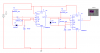
I'm trying to make a circuit using a 556 timer. I want both timers to be astable, such that when the first one is high, it sets the second one oscillating, then they both shut off when the first one goes low again.
I need to know, what do I connect the output of timer A to in order to get this to work?
I thought I would connect it directly to the reset of timer B, and when I model it that way on electronics workbench, it seems to work fine (except the first pulse is quite a bit longer than the following ones. I don't know why), but when I try it for real, it seems the reset pin doesn't actually do anything, except when it's grounded, of course. So far, I've only tested timer A on my real 556, but it oscillates whether pin 4 is connected to Vcc or not, (unlike what happens in my model).
So what should I do? Attached is a picture of what I'm trying to do, but even though it works in multisim, it won't work IRL, because pin 4 has nothing to do with making the timer work. I suppose I could use two 555's and connect pin 3 of the first one to pin 8 of the second, but Vcc is shared in the 556.
Attachments
Last edited:
