Continue to Site

Welcome to our site!

Electro Tech is an online community (with over 170,000 members) who enjoy talking about and building electronic circuits, projects and gadgets. To participate you need to register. Registration is free. Click here to register now.

  • Welcome to our site! Electro Tech is an online community (with over 170,000 members) who enjoy talking about and building electronic circuits, projects and gadgets. To participate you need to register. Registration is free. Click here to register now.

500w-220v inverter

Status
Not open for further replies.

aflatoon1989

New Member
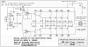
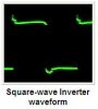
i was trying to build an inverter...but problem occurred when i try to simulate it on multisim i couldnt find the desired components in that...and i need to see the output wave form .....can anyone simulate for me...i just want the waveform.


parts tht are missing in multisim cd 4047 and c1061(transistor)
imge is attached....and the alternate i found on national instrument forum for cd4047 is also attached.
 

Attachments

  • 500w-220v-inverter(corrected).GIF
    500w-220v-inverter(corrected).GIF
    17.9 KB · Views: 2,088
  • monostable.zip
    40.9 KB · Views: 1,209
If you're hoping this will be a practical inverter for use as a UPS rather than just a school project you'll be sorely disappointed.
 
well before trying to build i hve to see the waveform of this and availability of components ...if all are right then i will think to build it up...but first i have 2 show the waveform of it to my teacher
 
The circuit was messed-up by MP the moderator (who was fired from being a moderator today):
1) It has half the number of 2N3055 output transistors for an output of 500W.
2) The output transistors do not have emitter resistors to equalize their gains so the transistors must be matched.
3) The circuit is missing diodes to arrest voltage spikes.
4) The resistor value in the oscillator is far too low and the capacitor value is far too high.
5) It uses two quad opamps instead of a single small dual opamp.

MP deleted my version of this simple old circuit that works properly.
 

Attachments

  • 500W inverter final.PNG
    500W inverter final.PNG
    201.1 KB · Views: 5,690
Look up the data sheet for the C1061 and see if you can modify a similar part in the simulator. You could simulate the square wave Q /Q with a signal generator in the software. Square waves are lousy for mains power inverters and only found on the cheapest / worst designs.
 
Many of those inverters are used in The Philippines where power Mosfets are not available. The output is a square-wave.

My electricity is very reliable so I don't have and don't need an inverter.
If I needed an inverter then I would buy a cheap lightweight Chinese pure sine-wave one.

Here is the waveform of a similar square-wave inverter circuit;
 

Attachments

  • square-wave inverter waveform.JPG
    square-wave inverter waveform.JPG
    6.3 KB · Views: 429
Last edited:
Status
Not open for further replies.

New Articles From Microcontroller Tips

Back
Top