Electro Tech is an online community (with over 170,000 members) who enjoy talking about and building electronic circuits, projects and gadgets. To participate you need to register. Registration is free. Click here to register now.
Welcome to our site! Electro Tech is an online community (with over 170,000 members) who enjoy talking about and building electronic circuits, projects and gadgets. To participate you need to register. Registration is free. Click here to register now.
I am using some kind of delay process to generate this pulse and I can't change it.
I am searching for a logical gate or something to do this automatically.
If the frequency of the pulse doesn't vary a tremendous amount, you could feed it to a PLL (no change in frequency) and then use the sine wave output of the VCO to drive a simple squaring circuit (a Schmitt trigger comes to mind here).
if the freq doesnt change (much) and neither does the pulse width you could use a schmitt trigger (74HC14 or make one out of a comparator).
With a low-pass filter with the input being the PWM and the output feeding the Schmitt. By putting a diode across the resistor pointing towards the schmitt you can choose the resistor and the capacitor to effectively stretch the pulse to be ~50%
otherwise use a toggle flip-flop to change it output from high-low-high at each leading edge. this will 1/2 your freqency, but there are simple circuits to double frequencies again using XOR gates and capacitors
Why can you change the circuit that makes this sub 50% duty? and why cant you duplicate it to have the 2nd make 50% duty?
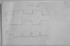
I am using the attached circuit to double my VARIABLE frequency,which produces a nonsymmetric pulse based on a not gate's delay.
Because I am feeding some and gates through latches and these are me latches enables,I need it to be perfect 50%,without change in frequency.
I am doing this in Xilinix Foundation's software's schematic editor which provides me with just simple logic gates.(no cap or IC)
Actually I am trying to make LS7084 IC through FPGAs.
But finally I reached my goal through another way with no 50% duty cycle pulse.
(but I still don't know how can I make my pulse symmetric with flip-flop without changing it's frequency :roll: )
It must have happened at about same time. Just before hitting
submit button I was called away from my desk to a meeting.
I tought I hit it but I gues I missed it. When I came back your post
was there already and I didn't check.
Mea culpa... :roll:
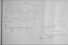
Z is the output with a positive edge clock input , with a negetive edge clock invert y and Z.
if you use a one shot you should be able to stretch the output to whatever you want plus you can use a positive or negetive edge to trigger it..
also what i have as Y input will follow F(in) with a negetive edge Clock input
with a positive edge Clock input Y is the oposite of F(in).
the width of Z or F(out) is the propagation delay of the exclusive Nor gate.as you said .
Yes,we can use two monostables (a positive triggered and a negative triggered) and then add their outputs to get it symmetric.
But as i said before I don't know how can I Make a monostable with basig logic gates I have in simulation editor.
Yes,we can use two monostables (a positive triggered and a negative triggered) and then add their outputs to get it symmetric.
But as I said before I don't know how can I Make a monostable with basic logic gates I have in simulation editor.
i connect the MR pin to vcc(5v) and the d pin to qnot pin .i get the input frequency to clk pin i get the output from q .but it didnt work.help me in that area?
This site uses cookies to help personalise content, tailor your experience and to keep you logged in if you register.
By continuing to use this site, you are consenting to our use of cookies.