Continue to Site

Welcome to our site!

Electro Tech is an online community (with over 170,000 members) who enjoy talking about and building electronic circuits, projects and gadgets. To participate you need to register. Registration is free. Click here to register now.

  • Welcome to our site! Electro Tech is an online community (with over 170,000 members) who enjoy talking about and building electronic circuits, projects and gadgets. To participate you need to register. Registration is free. Click here to register now.

5 IRF4905 P FETs in parallel

Status
Not open for further replies.

kinarfi

Well-Known Member
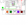
Any one have any Ideas about this idea. How much current would 5 IRF4905 P FETs in parallel handle, each is rated at 74 amps? My thought is to use them as a starter solenoid, in parallel with the starter motor solenoid which doesn't always work. I would tie all the gates together and feed them with an N FET rated for about 5 amps or so, with it's gate tied to the start terminal of the key. All mounted on a hefty piece of aluminum for a heat sink and a powerful schottky diode for protection.
Kinarfi
 
Last edited:
I would use NFETS instead as they typically have a lower Rds_on rating. Also, the 74A rating is the ABSOLUTE MAXIMUM, not an operating current. If you look further it degrades substantially with case temperature, so you'll have to derate them accordingly.

You're also going to need a pretty massive protection diode to handle the back emf when the starter shuts off.

This is not going to be easy to handle that much current out of TO220 cases. It would be easier to find the larger chassis mount transistors that have wire lugs, although probably more expensive.

In the end, an actual starter solenoid is going to be easier, cheaper, and probably more efficient too.
 
The problem is that he needs a high side driver for the starter, thus the NFETs would need a voltage higher than the battery. PFETs just require the gate to be grounded for high-side turn-on.
 
Oh, is the ground on the starter just the frame it's bolted to, so no way to insert a low side?
 
Correct on all accounts, back diodes would be MBR735, MBR745, The starter is on a recreation vehicle, not a car. a little less current, but still a bunch. Yep, starter is chassis grounded, eliminating N FETs
Kinarfi
 
So? Use a photo voltaic isolator, or a charge pump IC... This obviously isnt' for high speed switching so even a very basic charge pump IC would work great.
 
Look at the Rds-On spec not the rated current. For IRF4905 the Rds-On is 0.02 ohms with -10v gate bias. Not sure how much your recreational vehicle starter draws but my 30 HP generator starter draws about 30 amps. At 30 amps a single IRF4905 will have 0.6 vdc drop across it. If your ON duty cycle is just starting you can probably get by with just a single device. Again, if just used for starting, you don't need much of a heat sink since it won't have much ON time.

Source to battery, drain to starter, pull gate to ground to start. Put about a 1K resistor from source to gate to ensure off state. You do have to worry about starter inductive kick back voltage, so diode across starter motor is good idea. If your battery voltage drops you will also have less gate drive which will increase Rs-On of MOSFET. Put more then one in parallel will help for this situation.
 
Last edited:
The last time I looked at starters (many years ago, admittedly), the starter solenoid served two functions. Electrically, it acted as a relay (current amplifier) to drive the starter motor. It was controlled by the starter relay, which was in turn controlled by the ignition switch. Mechanically, it had a sprag clutch which engaged the pinion gear on the starter shaft with the ring gear on the flywheel.
The mechanical part was essential, as you don't want the starter motor permanently coupled to the engine.
MOSFETs can be used to drive the solenoid, but they can't replace it. At least, not in the system I just described.
 
Last edited:
The small engines have a separate starter relay with no mechanical connection to starter motor. I think most newer starters have a centrifugal throwout gear with spring loaded return.

For a MOSFET replacement you do have to worry about a bad battery. An 'ah-ah' starter grunt will put maybe 5-7 vdc at 30-40 amps across MOSFET.
 
I'm used to seeing starter currents of ~250A in my 470cu in Continental :eek: Good news: it is usually running by the time the prop makes ~ one revolution.
 
Last edited:
Thank you all, you have brought out stuff I need to consider more carefully, such as the voltage drop during cranking that could and probably would cause the gate charge to back off some and allow the Rds on to rise. I will look into charge pumps. And I'm so jealous anyone who gets to sit behind a running continental. The voltage drop problem my apply to other problems I have also.
Thanks Again,
Kinafi
 
I have another question about using FETs in parallel, and a comparison, if you put sever diodes in parallel you still have a minimum voltage drop of around .7 for forward biasing, does the same apply to FETs or are they just resistive, For instance, it was noted that IRF4905 has an Rds-On is 0.02 ohms with -10v gate bias, so at 10 amps, Vds would be .2 volts. If 2 were in parallel, would the Vds on each be .1 volts as if it purely resistive. Just wondering and learning, and in a neat place like this, I hope I'm helping others learn.
Thanks
Kinarfi
That's correct, as long as you have ≈10 volts Vgs (5V for logic level devices).
 
Thanks,
Kinarfi
 
MOSFET's in parallel are quite a bit different then diodes in parallel.

For MOSFET's as they get warmer their Rs-ON gets higher. This means that unbalances cancel out somewhat as the 'hot' MOSFET will begin to take less current as it warms up shifting more of the current to cooler MOSFET's.

For silicon diodes, as the diode gets hotter its voltage drop decreases making it take even more current from the other parallel diodes.

You still have issue with gate threshold variances (getting same Ids for same Vgs) between devices on MOSFET's but they don't create a run-away situation like diodes or bipolar transistors in parallel.
 
Last edited:
Thanks RC, I was using diode to show the voltage drop of the PN junction, even several in parallel as opposed to the resistance of FETs in parallel, but the info about bipolars was most interesting, don't think I realized that trait about PNs / bipolars.
Kinarfi
 
the easiest way to do it is to use a dc dc converter (there is very inexpensive type around 5$) and a bunch of N-Mosfet
ive made 100A 150V DC switch with 10 mosfet in parallel, i only loose about 10W of heat
 
the easiest way to do it is to use a dc dc converter (there is very inexpensive type around 5$) and a bunch of N-Mosfet
ive made 100A 150V DC switch with 10 mosfet in parallel, i only loose about 10W of heat

I'm looking into that idea, can you post your schematic? so I see what you did and maybe adapt it to my situations.
I'm thinking double the voltage and feed the gate via optic isolator or small FET. Without actually drawing, building and testing, my basic concern is the current draw created by the gate to source resistor, Would a DC to DC converter supply enough current at the higher voltage. The charge pump I'm looking at is Microchips TC7662A or B, <$2.00 @ Allied Electronics.
Thanks,
Kinarfi
 
i use dc dc converter like this one
Recom Power Incorporated - ROM-0512S - Allied Electronics (there is some similar even cheaper at digikey i think)
i supply 5v (or any voltage the converter is designed to use) input to the dc dc converter and i connect N mosfet gate directly to output of dc dc converter (i usually send 12 or 15 V) (you may add a small resistor in serie with the gate) then the n-mosfet is floating and can be connected either on low or high side of the load

this may be a little more expensive but a lot more versatile
 
I did some simulating and since my circuit already has an oscillator, I figure I can use it to create my own voltage double. May need to use a P and an N FET to get load handling capabilities, but it's fun and interesting to try oddball things. Then I can use some optoisolators and separate my control circuit from my power FETs and use N FETs only. Thanks for sharing your ideas and giving me ideas about different ways to accomplish my goals.
Thank You,
Kinarfi
I know we hate secrets here, but I'm not quite ready to share the full schematic yet. I'm afraid someone steal it, improve it, and beat me to the use of it. I think it's called paranoid.;) POST.PNG
 

Attachments

  • POST2.PNG
    POST2.PNG
    39.2 KB · Views: 589
Last edited:
Status
Not open for further replies.

Latest threads

New Articles From Microcontroller Tips

Back
Top