Continue to Site

Welcome to our site!

Electro Tech is an online community (with over 170,000 members) who enjoy talking about and building electronic circuits, projects and gadgets. To participate you need to register. Registration is free. Click here to register now.

  • Welcome to our site! Electro Tech is an online community (with over 170,000 members) who enjoy talking about and building electronic circuits, projects and gadgets. To participate you need to register. Registration is free. Click here to register now.

4th-Order Source Follower Lowpass Filter design

Status
Not open for further replies.

JondorZ

New Member
Hi there,

I have a project to design a 4th-order source follower lowpass filter for medical applications. Here are the specifications:
  1. Supply Voltage: 2.5V
  2. Filter order: 4th-Order
  3. Cutoff Frequency: 3kHz, 5kHz, 8kHz, 10kHz programmable
  4. Power Consumption: <2mW
  5. Design Tech: 0.35um CMOS

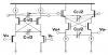
I am using Cadence Virtuoso to design and simulate the circuit. I am designing the internal circuit of the opamp using NMOS and PMOS transistors. So I use the biquad design and it doesn't seem to be working. I need help in whether the biquad design is suitable or there is other better circuit design. Thanks a lot!
 
Last edited:
Sounds like you are trying to do low-voltage CMOS OpAmp custom IC design. With a supply voltage of 2.5V, this is very difficult, and requires lots of experience and knowledge about the specifics of the the IC process.
 
yeah it is very difficult and i'm not experienced in IC design. That's why i need help.

It is a custom IC design for medical applications (usually low frequency ranging from 1kHz to 10kHz)

I have attached the circuit design i'm using. But i couldn't get the required simulation results.
 

Attachments

  • Fourth-Order Filter Schematic.png
    Fourth-Order Filter Schematic.png
    38.5 KB · Views: 506
A source follower can be used to generate a Sallen-Key topology active filter, which uses a +1 amplifier gain for the active device. Typically one section provides a two-pole rolloff, so a 4th-order rolloff would require two active sections.

To help with the passive part value selection you can use the free Filter-Pro software from TI. A simulation of the values generated by this software is then needed with the actual circuit components, to refine the values. You will likely have to adjust some of the values slightly, since the source-follower gain is slightly less then the ideal gain of +1 and it's output impedance is greater than the ideal of zero ohms, as assumed by the Filter-Pro software.
 
thx crutschow for the reply.. the filter-pro software helps to design the filter using op-amps.. may i know where can i find the MOSFET transistors schematic of the opamp? I am using Cadence and the library i'm using do not have opamp, and i need to build the opamp from scratch. thanks.
 
Status
Not open for further replies.

Latest threads

New Articles From Microcontroller Tips

Back
Top