Continue to Site

Welcome to our site!

Electro Tech is an online community (with over 170,000 members) who enjoy talking about and building electronic circuits, projects and gadgets. To participate you need to register. Registration is free. Click here to register now.

  • Welcome to our site! Electro Tech is an online community (with over 170,000 members) who enjoy talking about and building electronic circuits, projects and gadgets. To participate you need to register. Registration is free. Click here to register now.

4N35 optocoupler trigger LEDs circuit

Status
Not open for further replies.

ninarrr

New Member
Hi this is my first thread in this forum.

I am trying to drive a series of LEDs using a trigger signal. I want to isolate the power and ground of the trigger circuit and the LED circuit.

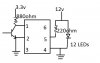
I have wired my circuit as attached and my LEDs are always on (full brightness) regardless of my input trigger signal. My understanding is that if the optocoupler is turned on then 12V will short to ground through the 220ohm resister instead of the LEDs.

I also tried connecting the LEDs between 12V and pin5 of the optocoupler but the LEDs are not as bright (but it triggers). I need to have the LEDs as bright as possible and also triggers depending on the input form the left.

Please tell me what I am doing wrong...
Thanks!

Nina
 

Attachments

  • trigger circuit.jpg
    trigger circuit.jpg
    24.3 KB · Views: 2,686
When I trigger my trigger input on the left I can measure a 550mV pulse between my pin4 and 6 of the opto-coupler so I am thinking my trigger circuit must be correct. Just somehow my LEDs are not wired appropriately.. I also tried removing the 220ohm on the right side the LEDs are still.
 
First your 12 LEDs will not illuminate on 12V as the forward voltage can be between about 2V and 4V for each LED depending upon color.
I would connect several parallel strings with current limiting resistors in each string between +12V and the pin 5 of the optocoupler. Leave pin 4 at ground as long as the 12V is connected between Vcc and ground.
Second you donot need a transistor connected to pins 1 & 2. If pin 2 is at ground and a resistor is connected from pin 1 to the other voltage the LED's connected to pin 5 will illuminate when there is current flow through the diode on pins 1 and 2.
 
Your circuit does not stand a chance of working.

Dont try to "short out" the supply, it will fry the opto.

Dont short circuit the diode in the opto to try and turn it off, use the transistor in series.

Are you connecting a string of LEDs in series across the supply without a current limiting resistor? Very basic error, can only end in smoking LEDs.

Have a look at my circuit, use one LED to get the thing working.

JimB
 

Attachments

  • 4N35 Opto.PNG
    4N35 Opto.PNG
    13.4 KB · Views: 7,505
Wow thats all messed up.
You dont need a transister on the input. Drive the input from your 3.3 volt trigger voltage and a resister.
You have the LEDS hooked up across the 12 volt supply, the photo transister or output needs to be in series with them.
 
Hi Jim, thank you for the reply. I actually did try hooking up the LEDs the way you did in the diagram here. Triggering works fine but my LEDs are a lot dimmer. I had a 220ohm in series with the LEDs which I think is quite small of a resistance already. These LEDs have built-in resistors. My LEDs are a lot dimmer than when they are connected directly to 12V power supply. I need them to be super bright. Do you have any idea what's making them so dim? I measure only a 5.6V across the LEDs but they are rated for 12V at 30mA. Seems like the optocoupler is eating away some of my voltage drop a bit too much.

Thanks again.
Nina
 
I need them to be super bright. Do you have any idea what's making them so dim?
If thay are 12 volt leds you can only use 1 across 12 volts. You need regular LEDs to put them in series, look up LED calculator.
 
Status
Not open for further replies.

New Articles From Microcontroller Tips

Back
Top