Continue to Site

Welcome to our site!

Electro Tech is an online community (with over 170,000 members) who enjoy talking about and building electronic circuits, projects and gadgets. To participate you need to register. Registration is free. Click here to register now.

  • Welcome to our site! Electro Tech is an online community (with over 170,000 members) who enjoy talking about and building electronic circuits, projects and gadgets. To participate you need to register. Registration is free. Click here to register now.

48v Gel Battery Monitor

Status
Not open for further replies.

juniorooo7

New Member
Hello . can some one help me build a 48V Battery Monitor . I have a bank of 4 battery`s 12V 200 AMp Conected to a solar Pannel and another saparate bank of 8 Batteryes 6V540A Conected to a 5KW wind turbine .
I would like to increase the battery spam life and keep them with discharge under 10%. So i would need a discharge monitor .
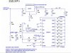
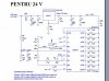
I found some schematics for 12V and 24V but i dont know how to modiffy them. Could some one help PLS :D
 
It sounds like you just need a voltage divider on the 24v circuit to turn it into a 48v detector.
 
I think it needs more then that . From what i know when you modify voltages you need also to recalculate the resistive part.
 
All that you need is to monitor the output voltage and then drop out a power contactor when the minimum voltage is reached. Normally, that will be between 1.9 volts per cell and 1.75 VPC. Alternative power systems normally use the 1.75 VPC @ 25°c as the cutoff point.

I have a 48 volt stack running a telephone system and since we keep them at normal room temperature, we only need to monitor the voltage. We are using Absolyte batteries so you can beat the crap out of them and they still have a 20 year life expectancy.
 
Post the circuit for 24v and we can work out the resistances for 48v


Here are the 2 12V and 24 V i found on the forum . The 24V i already build it for fun and it worked very good .

Also i had a 24V shunt regulator and when a friend of mine helped me modifiy it we also recalculate the resistive part of the entry curent.
 

Attachments

  • 12v.jpg
    12v.jpg
    65.7 KB · Views: 455
  • 24v.jpg
    24v.jpg
    63.4 KB · Views: 1,094
You will have to have 2 inputs. Put 24v on the input of the resulator, exactly as per the 24v circuit diagram.
Get another 102k resistor and connect it in series with the 102k resistor on the circuit to make 204k and put the new 102k resistor on 48v.
In other words, remove the top of the 102k on the 24v circuit and connect it to the bottom of the new 102k resistor and put the top of the new 102k resistor on the 48v terminal of the battery.
 
Do you have a source of 24V to power the circuits?
 
Yes .. I can wire it from the batteryes . Like this .. Also i have separate power for charging regulator, so from the right side il power the Monitor and from the left side il power the regulator.
 

Attachments

  • Alimentare_regulator_24V_la_48V.JPG
    Alimentare_regulator_24V_la_48V.JPG
    18 KB · Views: 350
Status
Not open for further replies.

New Articles From Microcontroller Tips

Back
Top