Continue to Site

Welcome to our site!

Electro Tech is an online community (with over 170,000 members) who enjoy talking about and building electronic circuits, projects and gadgets. To participate you need to register. Registration is free. Click here to register now.

  • Welcome to our site! Electro Tech is an online community (with over 170,000 members) who enjoy talking about and building electronic circuits, projects and gadgets. To participate you need to register. Registration is free. Click here to register now.

4017 oddness

Status
Not open for further replies.

fuper

New Member
Hi everyone.

I'm experimenting with a Cd4017 for the first time these past couple of evenings.

Right now I've got it in a breadboard powered by a regulated 5v supply [7805 regulated].

I've got all the inputs tied to GND except the clock enable which I've plugged into vcc.

I've taken three arbitrary outputs and connected them to a RGB led. Each output to the led has a 1k resister in series. To protect the led.

Okay - from reading about cmos and these types of parts i know I should not have inputs floating correct, random behavior could occur. Correct?

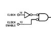
Seems that when I've hooked up the circuit as described above, I get somewhat random output on the led. It starts flashing, which is nice but not expected since I'm not making a transition from low to high on the clock input as its plugged into vcc

From the data sheet it indicates the clock would increment only on a transition from low to high on the clock input?

Anyway I'm just trying to wrap my head around this and I know I still have some debugging to do. I just cannot seem to get it to nicely transition from one output to the next. I've tried it with a single led to eliminate the complexity [complex to me anyway] of a RGB led. I've tried a switch to toggle the clock, I've tried leaving the clock line tied high etc.

Cheers,
Fuper
 
If you get any sort of clocking on the chip it is due to the 50/60Hz mains being detected by the clock-line.
That's why I always use batteries when experimenting. I learnt this 40 years ago.
I use batteries for two reasons.
Firstly they have a low current capability and if you connect up a circuit with a "short," the parts will not fry.
Secondly, a battery will not introduce hum.
 
Firstly they have a low current capability and if you connect up a circuit with a "short," the parts will not fry.

You cannot make that statement without specifying the battery type.
For example, a small 12V SLA - say 3AH - will certainly not have a 'low current capability'. Short that out , and the insulation on the connecting cables will probably catch fire almost instantaneously!!
Even some of the smaller alkaline batteries have a significant instantaneous current capability - enough to 'fry' incorrectly connected components.
Generally speaking, i would suggest that it is unwise to use batteries for prototype testing, without some form of current limit in series with the supply. Even if it's just a fuse.
 
If you are trying to use any sort of switch for the clock transition you are very likely to get voltage spikes going into that input... (many high's and lows happening very very fast) and that's what could be giving you "random" results... you could put a 10K pulldown resistor on the clk input and tie it to ground, that WILL keep it low until you apply a high... and also have you put the "reset" pin to ground as well? because its needed for normal function.
 
Last edited:
I suggest to check the VDD - CLK connection for good contact.

I can't imagine a 5V regulated power supply with its output voltage swinging between 3.5V (high input voltage) and 1.5V (low input voltage) for VDD=5V.

If you have an oscilloscope just check VDD for transients/ripple. If necessary add an electrolytic cap (100 to 470µF) at the input pin of the regulator.

As far as batteries are concerned there are just a few of them limited to low short circuit current (such as e.g. CR2032, which is also capable of frying CMOS-ICs).

Even a Lithium-Ion cell can deliver relatively high current for some seconds - enough to fry any reversely connected IC.

After all, it doesn't help much if a test circuit works well with battery power if it's intended to be used being supplied by a voltage regulator.

I always supply test circuits with the intended power source.

Boncuk
 
problem solved

Per shaneshane1 recommendation I added a 10k pulldown resister and this dramatically improved things. I also added a 100 uf [what I had at hand] bypass capacitor near the IC. This also helped.

I noticed with the switch I would still occasionally get a little occasional 'twitch' on the led.

I wired up a 555 in astable mode and hooked that to the input. I also put a bypass cap on the 555 as well since I've read that is necessary in these circumstances. When this was all connected the little twitch went away.

So I will conclude that the switch was not properly debounced causing problems,

Thanks for everyone's help. Such a simple experiment really helped me learn.

Just a bit more: the 4017 has no "CLOCK ENABLE", but a "CLOCK INHIBIT" (pin13). If this input is kept "H" the counter will do NOTHING and remain at the last count - provided the RESET input is "L".
 
Just a bit more: the 4017 has no "CLOCK ENABLE", but a "CLOCK INHIBIT" (pin13). If this input is kept "H" the counter will do NOTHING and remain at the last count - provided the RESET input is "L".

You sure about that? Most data sheets I have seen refer to pin 13 as a "Clock Enable" including this one from Fairchild. Not that it matters much I guess.

Ron
 
The clock enable is negative true. If it is called clock inhibit, it's positive true. I guess that's what you meant by "Not that it matters much I guess.".:)

Yep, pretty much what I was getting at. :)

Ron
 

Attachments

  • 4017 Input.jpg
    4017 Input.jpg
    2.8 KB · Views: 155
You sure about that? Most data sheets I have seen refer to pin 13 as a "Clock Enable" including this one from Fairchild. Not that it matters much I guess.

Ron

I'm sure about that, but there is no big difference since the action is unchanged (provided the right voltage level is applied).
NXP and ST use "Clock inhibit" on their data sheets.

Boncuk
 
Status
Not open for further replies.

Latest threads

New Articles From Microcontroller Tips

Back
Top