Continue to Site

Welcome to our site!

Electro Tech is an online community (with over 170,000 members) who enjoy talking about and building electronic circuits, projects and gadgets. To participate you need to register. Registration is free. Click here to register now.

  • Welcome to our site! Electro Tech is an online community (with over 170,000 members) who enjoy talking about and building electronic circuits, projects and gadgets. To participate you need to register. Registration is free. Click here to register now.

4 pole relay to reverse polarity in steps

Status
Not open for further replies.

nate4548

New Member
hi there all, :)

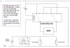
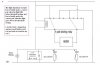
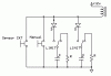
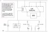
I am building a motor that has to turn a window shade, and am trying to make it automatic so that it opens when it turns light outside and closes when it turns dark.

https://i440.photobucket.com/albums/qq129/nate4548/4polerelay.jpg

now because it has to turn only until the shade closes I had this idea of using a latching relay and microswitches

using ball chain to open and close the shade. With stops that trigger the microswitches. the stops will hit this lock with springs that moves enough to allow the stop to hit the switch but then pull it back thereby reengaging the switch.

so here's the idea I use a 4 pole latching relay, when the light sensor activates it applys positive power to the relay starting in phase 1 will turn the motor clockwise and when the microswitch disconects momentarily and then reconects, it throws the relay into phase 2 shuting off power to the motor, when power is reapplied to the relay again the relay kicks into phase 3 throwing the motor in reverse (counter clockwise) until it hits the microswitch (momentarily shuting off and suppling power again) throwing the relay into phase 4 turning it off and so on...

now I know there are alot of things that are not going to work here because I'm kind of a noobee and was just using my imagination, but... I really want this to work. and because I'm not sure of all the exact concepts.

can anbody help me out here please??

I've uploaded a picture basically of what i'm trying to do.
please see my diagram at this link
https://i440.photobucket.com/albums/qq129/nate4548/4polerelay.jpg
 
Last edited:
There are many ways to do it. Attached are a couple of circuits that should work. They're pretty much the same. The relay selects the motor direction and the limit switches stop the motor at the end of travel. The motor will only move when the relay is changed and it moves in the opposite direction.
The first circuit has two extra components, D1/D2. But it allows the motor and limit switches to be connected remotely with only two wires.

One thing that will have to be addressed is that your light sensor must have hysteresis. This so that it doesn't frequently open and close the shade as clouds pass. Do you have a circuit for the sensor?

Ken
 

Attachments

  • MotorLimitSwtReverser 7.gif
    MotorLimitSwtReverser 7.gif
    17.8 KB · Views: 2,296
**********
EDIT
As mentioned later in this thread, this circuit is not workable.
 

Attachments

  • Curtains.JPG
    Curtains.JPG
    51.2 KB · Views: 563
Last edited:
John1,

Assuming that the latching relay is a standard 4-pole/2-throw (4PDT), there is nothing to stop the motor from running. As soon as it hits one microswitch, it trips the relay and reverses the motor. The motor then travels in the opposite direction until it hits the other microswitch. It again trips the relay, it reverses direction and continues to repeat the cycle of open>close>open>close>....never stopping.

Or is there something about the relay the is unusual?

Ken
 
Hi Ken,

Nice to see you're still taking an interest, i will have to up my game now.
Ive tried to use the OP's diagram as much as possible, it is not the way i would have approached this circuit at all, but he says he wants to use a latching relay as shown.
And micro switches, as shown.

This latching relay as drawn, would more correctly be descibed as 2 pole 4 throw, in that it has four positions and two moving contacts. However, i have left it as shown, it makes no difference to its action what its called.

You are quite correct in that the circuit i have drawn has a fundamental flaw.
Which is that each micro switch remains closed while the travelling part rests against it.
I had thought the cap would take care of that, but it wont while the microswitch remains closed.
That also prevents the over-ride button and the light driven contacts from being effective. So it wont work like that.

I'm still thinking this through.
I will leave that incorrect circuit in place, but i might put an edit to say that its not workable.

Cheers, John :)
 
Thank You KMoffett and John1 for taking a little of your time and helping me out, I really appreciate it.

KMoffett, from what I understand, I thing John1's idea looks like it could work,
unless of course I don't know what I am talking about... (which is possible as I've never worked with a 2 pole 4 throw relay before)

see my idea was that positive power would be applied to ports 1 and 7 while -ground is applied to ports 3 and 5, so when the light dependent circuit contacts then it sents a pulse to the relay throwing it into phase 1 therby turning the motor (clockwise) and qhen the stop on the ball chain hits the microswitch momentarily it would trigger the relay to jump to phase 2 (remember there is no power hooked up to ports 2 and 6) and so on.
(the light dependent circuit triggers the relay again throwing it into phase 3 (turning the motor counter clockwise) and then the microswitch throws it into phase 4.

Am I correct?

ps. John you are right about the 2 pole 4 throw. My idea was that the traveling part would not rest against the switch only the stop would hit the switch at it's time.

here i found a picture kind of what i want to do with the microswitches.
https://www.laureanno.com/drapes-4.jpg
https://www.laureanno.com/drapes-1.jpg
https://www.laureanno.com/drapes-2.jpg
https://www.laureanno.com/drapes-3.jpg
 
Last edited:
Hi,

Well ive had a re-think, and this offering should be ok, so long as the caps are not too big. They have to be big enough to operate the four position relay, but not so big that they might damage the other contacts in the
event that the press button or the light driven contacts were to close. Maybe a bleed resistor would help, or maybe a low value in line with the button and light contacts.

************

Arrangements like this are almost certain to need some sort of over-ride button, cos curtains can get stuck, or jam very easily. Some kind of cut-out on the motor would be needed too.

************

I am wondering if the un-used contacts could be used to stop any over-run by wiring them as a motor short, but i dont think that over-run is likely to be a problem.

************

At a guess, i would say that a cap of about 1000 MFD (@ 12v) would be as big as i would care to short with ordinary contacts. In normal use, it would be unlikely to have to operate quickly enough for most electrolytics to retain much of a charge anyway. I would hope that two or three hundred MFDs would be enough to operate the four position relay.
If this assembly runs at a higher voltage then the caps would be lower values and definately want bleeds.

************

Better still, use a completely different approach to the relay circuitry, as shown earlier in this thread.
A four position latching relay is not how most people would make this arrangement.

***********

Best of luck with it, John :)
 

Attachments

  • Curtains2.JPG
    Curtains2.JPG
    62 KB · Views: 409
Nate,

I have to agree with John:
A four position latching relay is not how most people would make this arrangement.

Do you already have the 2P4T rotary relay. They are not common and are likely to be very expensive. I would recommend the cheap and easy 2P2T relay circuit.

But that said, the attached might help with John's solution. Since most microswitches are SPDT, the second contact could be used to assure the discharge of limit-switch capacitors. The resistors limit the current to an acceptable value. The diodes prevent the manual switch and the light-sensor's switch from having to pass large discharge currents from large capacitors.

Ken
 

Attachments

  • MotorShade2P4TSwitching.gif
    MotorShade2P4TSwitching.gif
    8.6 KB · Views: 660
I have one point to make, that the name 'latching relay' being used here is incorrect. A latching relay is one that has only two states, set and reset. A latching relay may have two coils, where the relay is set or reset depending on which coil is energized last, or one coil where the polarity of the current last applied determines which of the two states if goes to.

What you have drawn up, a relay with four mechanical states that steps with each activation of the coil is called a stepping relay. Some stepping relays have two coils, one to step one state with each application of current and a second overriding 'reset' coil that forces the coil back to the first position.

So while using the correct name for the relay doesn't help make the circuit work or not work correctly, however it should be stated anyway for the record. ;)

Lefty
 
Last edited:
thanks Leftyretro,

guys what do you say to this?
is there such a thing as a timed relay? that way i can skip the whole limit switch thing
 
Hi Ken,

Again you surprise me with your ability to spot a neat solution.
I had briefly thought about the un-used contact on the micro switches, but i did not think of that. The arrangement you suggest means that it is not necessary to find the minimum capacitor that would work the coil of the four position switching relay, just any reasonable couple of caps.
We have both assumed that 12v is the most likely supply, but i dont think the OP has mentioned the power supply at all.

**********

The light sensor has not really been addressed yet, i think that small opto-relay units are available which might just fit the bill.

**********

Hope you dont mind me re-drawing the unit, with the diodes and discharge resistors included.

Regards, John :)
 

Attachments

  • Curtains3.JPG
    Curtains3.JPG
    65.8 KB · Views: 277
Leftyretro is right, we should have been referring to "stepping" relays. Though there are single-coil, continuous-rotation stepping-relays. But why are you avoiding the cheap and simple. Yes, you can make timing circuits to control the motor rotation, but that assumes the shade mechanism is perfect, and I can assure you that over time travel times will change. That's why people opt for limit switches.

Ken
 
thanks Leftyretro,

guys what do you say to this?
is there such a thing as a timed relay? that way i can skip the whole limit switch thing

When you think about it this is the same requirement of most electric garage door opener circuits. They use limit switches at the full closed and full open position to remove power and reverse motor voltage for the next cycle.

Why don't you search for garage door circuits, probably just need two limit switches or optical switches and one or two standard DPDT relays.

Lefty
 
thanks Ken,

John, I like your modification. here's a question can you do me the honor of makings me a full schematic? (including Ken's idea about the 2P2T relay)
I really am jumping out of my skin as it's going to be the biggest project I did as of yet.

and I think 12V is probably the way I'm going to go.

thanks a mill. :)
 
Nate,

Go back to the second posting (mine) on this thread. That's the garage-door circuit that Lefty is talking about, and the cheap and simple 2P2T relay circuit that I have been I've been referring to. It's pretty much a standard for what you are trying to do.

Ken
 
ken,

what keeps this configuration your talking about from going clockwise and then when the limit switch is hit going right back counter clockwise?
 
If you look at either of my circuits, when the limit switch is hit, it stays open and it cuts the power to the motor. When the polarity is reversed, by the relay change, then there is a current path through the other limit switch, and the motor starts moving in the opposite direction.

Ken
 
I'm sorry Ken but I'm not understanding, there must be something I'm missing.
are u refering to this circuit?
https://www.electro-tech-online.com/attachments/motorlimitswtreverser-7-gif.25430/

Yes. Either of these two circuits will work. It totally replaces the 2P4T stepping relay circuit we were discussing. The transistor/resistor/diode connected to the relay, are used to drive the relay from yous light sensor circuit (?).

If you are going to stay with the stepper relay concept...do you have a source for the relay and spec's on it? Do you have a schematic for you light sensor circuit?

Ken
 
Ken,

I like your idea, the reason I was not understanding was because I thought we were just applying momentary pressure to the limit switch (therby opening the circuit right back again)

I don't know yet as of now which light sensor I'm going to go with. (any suggestions?)

And here's a question, from what I understand, the relay is getting constant power, so is the relay going to go into phase 2 just by getting a surge of power from the transistor/resistor/diode.... ?

Nate,
 
Status
Not open for further replies.

Latest threads

Back
Top