Continue to Site

Welcome to our site!

Electro Tech is an online community (with over 170,000 members) who enjoy talking about and building electronic circuits, projects and gadgets. To participate you need to register. Registration is free. Click here to register now.

  • Welcome to our site! Electro Tech is an online community (with over 170,000 members) who enjoy talking about and building electronic circuits, projects and gadgets. To participate you need to register. Registration is free. Click here to register now.

4-contact wind-vane to 8-light box

Status
Not open for further replies.

LAJay

New Member
Hello all.... a very low tech question (maybe refreshing? or interesting at least!) Pics below!

BACKGROUND:
I have a 1800's style US Weather Bureau mechanical wind-vane device, with a later style (1950's - 60's?) indicator-light panel. When I got them, no wires connected the two together. There must have been a tube type answer before, but if I can fit the "new" interface in the existing light box, which has room at the corners (the lights are in a circle), I'll use any solution.


DESCRIPTION
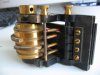
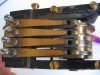
Simple enough: the wind-vane contact device is heavy brass by Julien P. Friez (Balt.) in the style of a music-box; there are 4 output terminals and a ground terminal. The 4 raised areas on a spool close 1 or 2 of the 4 brass contact outputs when the spool rotates. The elevated sections overlap so that when the wind is between N and E say, both N and E contacts close.

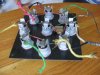
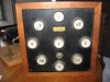
The display panel is by MC Stewart (Boston), and has N, E, S, W, and NE, SE, NW, SW, and "V" lamps (I assume the V means voltage). with on/off switch inline with a common ground to all 8 lamps, and each lamp has it's own a wire going to the center post. However, I can't tell what type of lamps these are, DC I assume. They're like auto-side light types: small, glass is same witdth as the base, with fairly bright blue insulator keeping the two terminals apart. It is a modern screw-in lamp. Has "46" stamped in black on the base, but nothing else. 2.7 ohms across the terminals.

IN SHORT:
Soooo... I have a "simple" 4-input to a 8-output application question!

MY BACKGROUND: (!) I have a background in Computer Science, with electronics. I can put together any circuit, but being unpracticed, I'm embarrassed to say I can't get anywhere past a crude and voluminous "and" gate solution, and don't even remember if I can put voltages through that AND-gate solution anyway without burning the place down.

I did draw up a truth table, but I can't remember what to do with it since I don't have a single binary output...

N, E, S, W, Condition

0 0 0 0, <NA>
0 0 0 1, W
0 0 1 0, S
0 0 1 1, SW
0 1 0 0, E
0 1 0 1, <NA>
0 1 1 0, SE
0 1 1 1, <NA>
1 0 0 0, N
1 0 0 1, NW
1 0 1 0, <NA>
1 0 1 1, <NA>
1 1 0 0, NE
1 1 0 1, <NA>
1 1 1 0, <NA>
1 1 1 1, <NA>


Now the pitch! Where do I go from here? How much voltage am I likely to use (and DC?); Is there some kind of a 4 bit D-to-A converter I need? The current likely went through the contacts (they are burnt/worn like it would over time), but I assume with an elegant solution, the current in wires going from the contact switches into the display light box can be separated from the current that lights the bulbs. (for fire safety)

Thank you so much in advance for being here to answer questions like this!!!! I appreciate any help anyone can give me!

Jason
 

Attachments

  • Aug21 082 (Medium).jpg
    Aug21 082 (Medium).jpg
    59.1 KB · Views: 240
  • Aug21 083 (Medium).jpg
    Aug21 083 (Medium).jpg
    59.9 KB · Views: 315
  • Aug21 084 (Medium).jpg
    Aug21 084 (Medium).jpg
    69.5 KB · Views: 224
  • Aug21 088 (Medium).jpg
    Aug21 088 (Medium).jpg
    68.5 KB · Views: 220
Last edited:
there are a lot of ways to do this electronically. the simplest way I could think of is to use a 4-16 demux like the 74HC154. Use the 4 contacts as the 4 inputs. select the 8 output pins that correspond to the correct terms. Run them into a ULN2803A darlington array which will drive 8 lamps. This could drive 500 mA lamps (6 W at 12V). If you want more, you will need higher capacity drivers.

However, I can't help think there is a very simple solution that uses some sort of cancellation that prevents, for example, E & N from lighting but allowing NE to light. It's too late for me to ponder it.
 
Hi Jason,
Looking at the pics, it looks as though the cams/switches maybe already 'coded'.[ they don't look like quadrants?]

Can you post a sketch of the 4 cams, that is, highs/lows and in the same orientation as they are mounted?

The lamp holders appear to be threaded, more like a lamp type screw bulb, with a single centre pole.

If you have a 0 to 12Volt dc power supply, connect one lamp, start at 0V from the psu and turn up the voltage very slowly
do this until the lamps appear bright enough to illuminate the legend.

Lets know what you get.
 
Last edited:
Your discrete logic chip solution would work.

You could also use a microcontroller and implement the same AND, NAND, OR, NOR, XOR logic in software or simply implement your existing table as a 16 element constant array of 8 bit output values;

Code:
;
;   input         lamp outputs
;  N,E,S,W     N NE  E SE  S SW  W NW  N
;  0 0 0 0 --> 0  0  0  0  0  0  0  0  0   n/a
;  0 0 0 1 --> 0  0  0  0  0  0  1  0  0
;  0 0 1 0 --> 0  0  0  0  1  0  0  0  0
;  0 0 1 1 --> 0  0  0  0  0  1  0  0  0
;
;  1 1 1 1 --> 0  0  0  0  0  0  0  0  0   n/a
Read the 4 bit Weather Vane encoder data on 4 input pins and use that value (0..15) as an index into the array. Copy the array value to an 8 bit output port connected to sink or source drivers or solid-state-relays or whatever to drive your lamp circuit. You could conceivably do it with a single 14 pin microcontroller, 8 transistors, a regulator, and a few resistors and caps'...
 
Last edited:
Hi
The switch cams are cut to suit a pattern as per the attached GIF.

The High of the cam closes the corresponding switch.


Mike.
Did you get my PM?
 
Last edited:
hi Jason,
Added a simple cam/lamp test circuit to the drawing.
 
Last edited:
I assumed that LAJay wasn't familiar with microcontrollers. The demux is pretty easy to do and is either cheaper or the same cost.
 
Yes, a 4-to-16 demux' solution would work too, and without using a microcontroller. I was simply offering an alternative to your excellent suggestion.
 
wow. thank you for the replys.

I went right up to Fry's and RS to look for the demux solution.

Found the 74hc154, but not the uln2803a. Fry's referenced that to a NTE2018, but didn't have it. Had a 2019, but that was PMOS i think, and I don't know if that will work.

I tested the bulb in a PS on display (Fry's is great!) and got this: at 5v, it was drawing 210ma, and at 6v it drew 240ma. Since only one light lights at a time, is it possible to use NAND or other GATES to do this with that little current? I am basically capabable of all your solutions, however I would need a bit more info to go on with either the DEMUX or MC solution, like assistance with any resistors, or the alternatives for a TTL driver...

I only have a breadboard to piece this together, no MC software etc... FYI, I used to program 65c02 on Apple IIe as a teen in the 80's, and remember doing some MC work in college. But I'm short on current details on doing anything other than looking at spec sheets and spending days figuring out a resistor value! I can work of a logical layout diagram of a complete circuit, or should be able to read a schematic ok as well...


MIKE: I didn't get your PM.... ??

Thanks again! Hope to hear from you guys again!

Jason
 
Last edited:
the nte will probably work ok. You could also use 8 small signal NPN transistors like 2n2222 or 2n3904. the 2803 is just more compact and carries a bit more current. No, you need to drive each bulb independently.

The following is how you would use a transistor. replace the coil and diode with your bulb. I'd use 1k ohms for R1. R2 isn't necessary but doesn't hurt - 100K would be fine. The '154 would feed R1. q1 is any NPN transistor that can carry 250 mA (Ic from the datasheet). Use one of these per bulb.
**broken link removed**
 
Last edited:
Those two ICs, a regulator, filter cap', bypass caps, and a flux' capacitor (grin)...
 
Last edited:
hi Jason,
I was under the impression you wanted to rewire the two devices as they were originally wired.

If you check the highs/lows on the cams driving the switches I expect you find that they are 'encoded' as I have shown my drawings.

IMO you dont need semi-conductor logic to drive the lamps from the cam switches, remember the circa dates 1800's 1950's, no semi's as we know them today.

If you want to upgrade the electronics I would still suggest that you checkout the cam encoding, its most likely not binary:rolleyes:

this was for MikeK8LH
MIKE: I didn't get your PM.... ??
 
Eric, please explain the "encoded"... i'm curious what this means. But continue reading to get an idea of what i understand it to be...

I don't think original rewire is possible, since the original (1800's version) was to a pen register (only 4) and not 8 lights. So, I must assume someone took this cam later in the 50's-60's, decided they wanted to get fancy and see a light for "NW" alone instead of simply seeing "N" and "W" lights lit together, and there was some other solution - heck, this may have been done with circuit processors if it was done in the 70's or 80's. i'm just guessing about the 2nd life it has lived. I don't really need "original" or the "50's/60's/70's" spec logic. If modern stuff works better/cheaper, then so be it. If another way works (simpler is more elegant) like it might have in the 1800's, that would be fun too... How would they have made 8 indicators for 4 terminal switches? Interesting question, even if I don't implement it.

upon testing per your diagram, i hook up 4 lights (leaving 4 not hooked up) to the 4 cam terms (as you specified): n-n, e-e, s-s, w-w. when i rotate it, it performs as i expected, and I see in your drawing. Here are the results:

When starting at N, N is lit alone. Rotating through toward E you will see N and E light up simultaneously for the same time N and E light up independently. i.e. the lit order goes like this: N (for 45deg); N+E (for 45deg); E (for 45deg); E+S; S; S+W; W; W+N. (in theory, roughly 45deg for every light, right? NE is lit from 22.5deg to 67.5deg; east becomes lit at 67.5 and through to 112.5 )
So I believe my truth table in the first post tell the correct story (yours may, but i just don't see it) and where 1 is on, 0 is off. yours was opposite maybe?

mine:
N-E-S-W --> desired light (1 of 8)
1-0-0-0 --> North lights up
1-1-0-0 --> NE (the intended behavior is to not light up the N or E at all, but light up NE (like an AND gate from N and E)
...

So it looks like the 4-16 '154 chip and the 2019 will do. But I now need to know what pins to connect to the NTE2019, and what caps I might need. If I'm already using a regulated (for sure, not a cheapy wall wart) power supply with 12 volt output, what resistor do i need for a drop to 5.4volts (that's what my 4x1.5 batteries tested in actuality, and the lights were perfect. If I need to use 6v, as it looks like the NTE2019 requires it, then the resistor value to get me from 12 to 6.)

The other confusing point to me is the requirement of the "enable gate" in the '154. what is that, and how do I implement it? just tie it to ground?

Also, is my electricity running all the way through the contacts, and into the chips, or do i have separate voltage/currents going into the chips for the 4 inputs and the 2019 output voltage/current? sorta like how a relay works, small currents control large isolated ones - will I have two loops? know what i mean? Do I want two loops for better safety?


Thats all - as long as it works, and now that I have the two main chips for less than $6, I can rest assured this "new" demux solution will not be more than $20 which is good.

so i really need help with the hookups and identifying any additional parts.

Thank you very much. This is a great encouragement, to be able to get near-live help. that's whats held me back from taking on small little projects like this in the past. Now I'm excited to learn again!

Jason
 
Last edited:
Hi Jason,

>>> So it looks like the 4-16 '154 chip and the 2019 will do. But I now need to know what pins to connect to the NTE2019, and what caps I might need. If I'm already using a regulated (for sure, not a cheapy wall wart) power supply with 12 volt output, what resistor do i need for a drop to 5.4volts (that's what my 4x1.5 batteries tested in actuality, and the lights were perfect. If I need to use 6v, as it looks like the NTE2019 requires it, then the resistor value to get me from 12 to 6.)

The 74HC154 and NTE2019 will work from a 6Volt supply and the NTE2019 inputs will be compatable with the 74HC154 at 6Volts.
You cannot drop from +12V to +6V in a controlled way using a resistor, as the lamp loading changed, so would the "6V".
You require a +6V regulator that will step down the +12Vdc from your psu.
If you choose 6V lamps with the lowest wattage rating that suits the psu and +6Vreg,,, remember W=V * I, if the current was say 100mA, this would give 6*0.1=0.6Watt lamp rating
OR you could use 12V lamps and run them from the +12Vpsu and use the +6Vreg just for the logic, [this would be my choice]
Do you plan to link this system to a PIC or MCU?

>>> The other confusing point to me is the requirement of the "enable gate" in the '154. what is that, and how do I implement it? just tie it to ground?

Yes, connect the Enables G0/1 to 0Volts.

>>> Also, is my electricity running all the way through the contacts, and into the chips, or do i have separate voltage/currents going into the chips for the 4 inputs and the 2019 output voltage/current? sorta like how a relay works, small currents control large isolated ones - will I have two loops? know what i mean? Do I want two loops for better safety?

Did you have to use the metal frame of the cam housing as the common return when you did the battery lamp test??
My only cause for a little concern would be the 'quality' of the contacts on the cam housing when they are conducting the low level currents at +6V, you may have to use pullup resistors on the contacts in order to electrically 'wet' the contacts..
I good clean with meths spirit would be a good idea.

>>> Thats all - as long as it works, and now that I have the two main chips for less than $6, I can rest assured this "new" demux solution will not be more than $20 which is good.

so i really need help with the hookups and identifying any additional parts.
 
Last edited:
hi Jason,

Attached pdf should be a start off pointer.

This drawing edited.... invertors added after 74HC154
 
Last edited:
Nice drawing and solution Eric.

Couldn't you eliminate the 74HC14 invertor? Does it matter if the inputs to the mux' are True Lo or True Hi?
 
Mike said:
Nice drawing and solution Eric.

Couldn't you eliminate the 74HC14 invertor? Does it matter if the inputs to the mux' are True Lo or True Hi?

Hi Mike,
I suspect that the metal cam housing is the common return and that the contacts are normally open. I didn't want to have the housing at +6V.

Without actually getting my hands on the device I have had to make some assumptions.

I have a 'gut' feeling that the cams are not coded high/low in a binary pattern:confused:

Thats why I couldn't post a complete drawing.


EDIT: Added invertors on the 74HC154 outputs..... above drawing changed
 
Last edited:
The 4 for wire output is surely just the result of the contact switches. Though one could argue that the output is, indeed, encoded (8 of 16).

Drop the inverters. There are 16 output combinations from the cam switches. The 4-16 demux will fully decode all combinations so no need for the inverters. (for example 0011 from the switches will be output 3 non-inverted and output 12 if inverted) - just pick the correct output from the '154.

I think the 2016 is a high side driver (check me on that, it's not totally clear to me from the datasheet) so you will need to use the "inverted" output of the '154. By that I mean use the output that corresponds to the inverted input. So, if NE is input as 0011, use the '154 output that corresponds to the 1100 input. The outputs of the 2016 would go to the lamp and the lamp to ground. Use moderately high resistors between the '154 and 2016. I'd say 4.7K or even 10K.

On the point about how this worked before electronics - I think there has to be an elegant solution there.
 
Status
Not open for further replies.

Latest threads

New Articles From Microcontroller Tips

Back
Top