Continue to Site

Welcome to our site!

Electro Tech is an online community (with over 170,000 members) who enjoy talking about and building electronic circuits, projects and gadgets. To participate you need to register. Registration is free. Click here to register now.

  • Welcome to our site! Electro Tech is an online community (with over 170,000 members) who enjoy talking about and building electronic circuits, projects and gadgets. To participate you need to register. Registration is free. Click here to register now.

4 bit synch counter and 7 seg decoder

Status
Not open for further replies.

andy257

Member
Hi Guys

Trying to get my head around this problem

Its a simple circuit really but funny enough its giving me some problems. I dont know if its the sim package or just me???

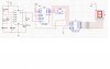
Using a 555 to generate a slow clock signal to drive a 4 bit synchronus counter. Connected this up to a 7 seg driver and 7 seg display.

When powered up all i get is a continuous lit up 7 seg.

Using a 74ls16 counter, 4511bd decoder, common cathode 7 seg, 555 timer.

can anyone see whats wrong??

oh and i have reset the count at 9 since thats all the 7seg can display.

Andy
 

Attachments

  • 7seg_183.jpg
    7seg_183.jpg
    112.2 KB · Views: 734
I think you should make the LT and the BI inputs of the 4511 to Vcc.
On cmos IC's one should never leave input pins floating, they need to be tied high or low. The LT when is low all segments are turned on. Leaving it floating is probably the problem.

Also no need to have the resistor from the output of the 555 to ground.
The 10pF capacitor on the control should be changed to about 0.1uF.
 
k7elp60 said:
I think you should make the LT and the BI inputs of the 4511 to Vcc.
On cmos IC's one should never leave input pins floating, they need to be tied high or low. The LT when is low all segments are turned on. Leaving it floating is probably the problem.

Also no need to have the resistor from the output of the 555 to ground.
The 10pF capacitor on the control should be changed to about 0.1uF.

Yep its working now, thanks alot.

Funny i didnt even notice them inputs without a connection

cheers

Andy
 
Two supply voltages without any logic level conversion?
With a 10V supply, the TTL counter might release some of its majic smoke.
With a proper 5V supply for the TTL counter then its logic high voltage won't be high enough for some Cmos 4011 and 4511 ICs.
Use a Cmos counter.
 
audioguru said:
Two supply voltages without any logic level conversion?
With a 10V supply, the TTL counter might release some of its majic smoke.
With a proper 5V supply for the TTL counter then its logic high voltage won't be high enough for some Cmos 4011 and 4511 ICs.
Use a Cmos counter and the same supply voltage for the ICs.
 
I'd just run the whole shootin' match on a 5v rail.

If that 2.2nF timing cap happens to be ceramic, timing resistors with that kind of precision will be pointless because of the cap's tempco.

Are there any synchronous CMOS counters (other than 74Cxxx types)?

Dean
 
Status
Not open for further replies.

Latest threads

New Articles From Microcontroller Tips

Back
Top